Chapter 2 • Antenna parts and required tools
8
1037312-0001 Revision B
Antenna kit
components
This section describes the main components of the 0.98 m
antenna kit:
•
Az/El and reflector bracket assembly
•
Antenna reflector
•
Feed support arm and support rods
•
Feed horn
•
Mounting parts for radio assembly
For details see Description of main components on page 10.
Related components
The following are related components that are not part of the
antenna kit:
•
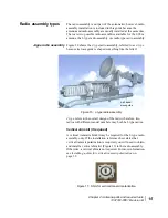
Radio assembly (J-type or cradle-type) – See Radio assembly
types on page 15.
•
Antenna mount – For general information about antenna
mounts, see Installing the antenna mount on page 4.
Two antenna kits for
two radio types
You can install the 0.98 m antenna with either of two radio types,
the J-type radio or cradle-type radio, which are described in
Radio assembly types on page 15.
To support these two radio types, the antenna kit is available in
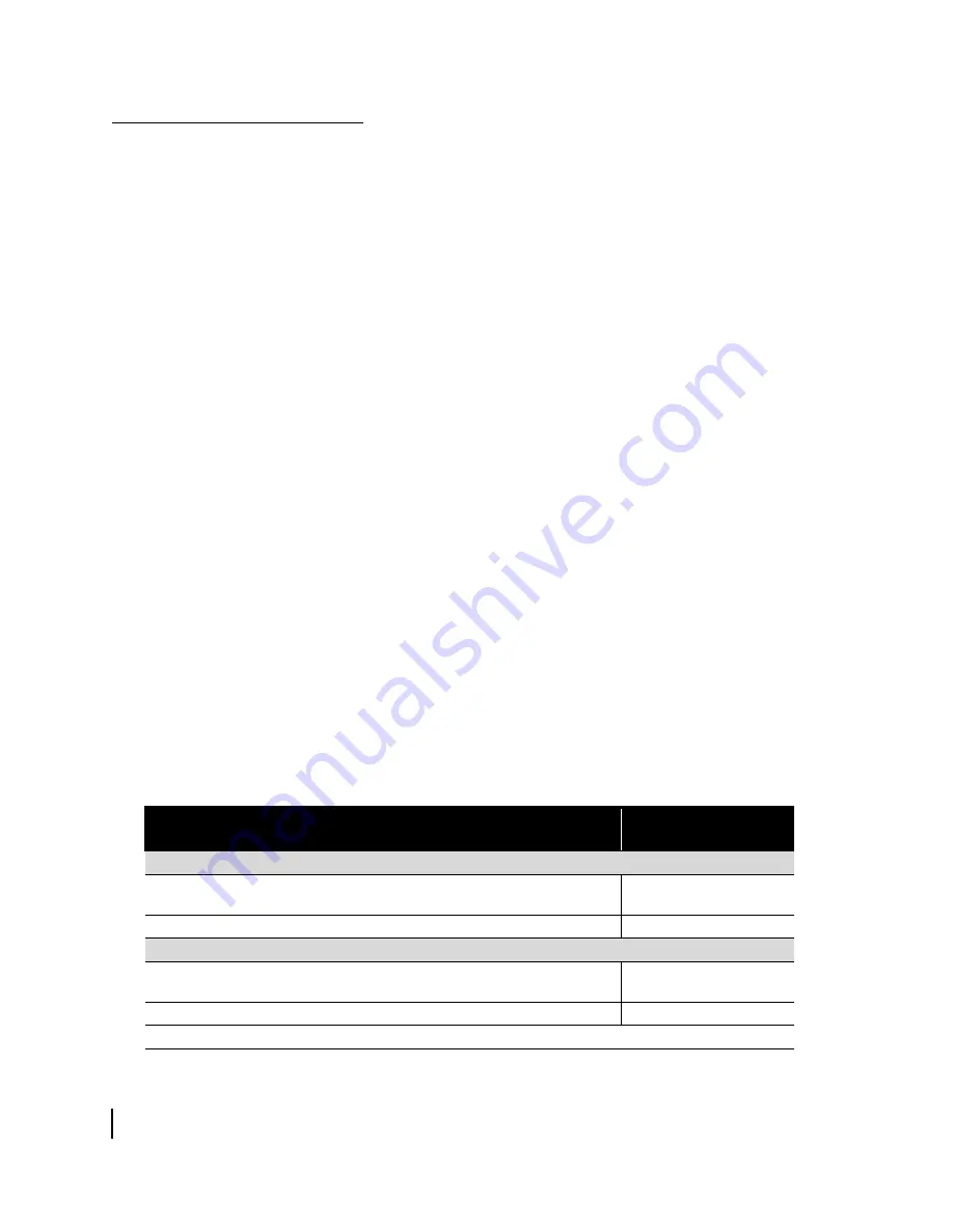
two configurations, as listed in Table 1. In this guide, the antenna
kit is used to refer to either kit.
Each antenna kit consists of two boxes of parts, as detailed in
Figure 2. Most parts are common to both antenna kits. The main
parts that are different in the two kits are the feed support arm,
support rods, and parts used to mount the radio assembly.
Before proceeding, refer to Table 1 and make sure you have the
correct antenna kit.
Table 1: Two antenna kit configurations
Box contents
Hughes part number
for each box
Antenna kit for J-type radio
Box 1 – Az/El and reflector bracket assembly, feed horn, mounting brackets
and adapter for radio assembly, waveguide transition, and other parts.
P/N 1501111-0001
Box 2 – Reflector, feed support arm, support rods, and other parts.
P/N 1501111-0002
Antenna kit for cradle-type radio
Box 1 – Az/El and reflector bracket assembly, feed horn, adapter for radio
assembly, and other parts.
P/N 1501111-0021
Box 2 – Reflector, feed support arm, support rods, and other parts.
P/N 1501111-0022
Box 1 is labeled
Box 1 of 2. Box 2 is labeled Box 2 of 2.
Summary of Contents for AN6-098P
Page 6: ... Contents vi 1037312 0001 Revision B ...
Page 10: ... Tables x 1037312 0001 Revision B ...
Page 22: ...Chapter 1 Overview 6 1037312 0001 Revision B ...
Page 46: ...Chapter 3 Assembling the antenna 30 1037312 0001 Revision B ...
Page 58: ...Chapter 4 Installing a J type radio assembly 42 1037312 0001 Revision B ...
Page 72: ...Chapter 6 Cabling and connections 56 1037312 0001 Revision B ...
Page 92: ...Chapter 7 Pointing the antenna 76 1037312 0001 Revision B ...
Page 94: ... Acronyms and abbreviations 78 1037312 0001 Revision B ...


