background image

Scope of this user guide

This user guide describes the features and operation of the HN9200 satellite modem, which
provides you Internet access by satellite. This guide also provides certain reference information,
such as the meaning of the modem’s front panel LEDs.

Audience

This guide is intended for users of the HN9200 satellite modem.

The satellite modem’s role

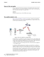
Figure 2: Role of the HN9200 in a satellite network

on page 2, illustrates how the HN9200

satellite modem provides connectivity and functionality that allow a computer, Ethernet device,
or LAN to connect to the Internet by satellite.

Figure 2: Role of the HN9200 in a satellite network

This illustration shows the HN9200 with a single computer host. However, the satellite modem
may also be used in a multiple-host configuration, in which hosts on a LAN share satellite Internet
or intranet connectivity through an Ethernet hub, router, or wireless base station. A host may be
a computer using Windows, Mac OS, or another supported operating system.

Note:

You must provide and configure hub, router, or wireless base station equipment if

any of these are used.

Even though the HN9200 satellite modem is typically connected to a host, it is

self-hosted

,

meaning it can operate without a host. it does not depend on a computer to establish and maintain
the Internet or intranet connection. However, the modem must be connected to a satellite antenna.

The Hughes Internet Gateway is a Hughes-operated satellite station that provides a connection
between the Internet and the satellite. The gateway routes data to and from the Internet and to
and from the satellite. The satellite transmits a signal to the antenna, which is passed to the
satellite modem to provide Internet connectivity.

HN9200 Satellite Modem User Guide

2

1038623-0001 Revision B

Satellite modem overview

Chapter 1

Summary of Contents for HN9200

Page 1: ...1038623 0001 Revision B March 2 2011 HN9200 Satellite Modem User Guide ...

Page 2: ...t to ensure the correctness and completeness of the material in this document Hughes Network Systems LLC shall not be liable for errors contained herein The information in this document is subject to change without notice Hughes Network Systems LLC makes no warranty of any kind with regard to this material including but not limited to the implied warranties of merchantability and fitness for a par...

Page 3: ...l Center 8 Creating a shortcut to the System Control Center 8 System Control Center home page 8 Text links 9 Common features on System Control Center screens 10 Button links 11 System Status button 12 IPSec icon 13 Links in the left panel 13 Small icon on System Control Center screens 14 Status and information screens 14 Red flag indicator 15 Features you may not see 16 System Status page 16 Recep...

Page 4: ...g for viruses and firewall issues 42 Cannot access the System Control Center 42 Satellite modem connected directly to a computer 42 Satellite modem connected to an Ethernet device 42 Using the front panel LEDs for troubleshooting 43 Power LED off and one or more LEDs flashing 44 All LEDs flashing 44 All LEDs off 44 Checking the Power LED 45 Checking the LAN LED 45 Problem with a connected device 4...

Page 5: ...figuring Windows Vista to use a static IP address 63 Configuring Windows XP to use a static IP address 64 Configuring a Mac computer to use a static IP address 66 Configuring proxy settings 67 Appendix B Home networking 69 Wireless network basics 69 Ethernet wired network basics 70 Appendix C Standards compliance 73 Safety Operating conditions for Canada 73 Repairs in Canada 73 Electromagnetic int...

Page 6: ......

Page 7: ...tion page 22 Figure 20 Port Forwarding Configuration page 23 Figure 21 Entering port forwarding rules 24 Figure 22 Download Allowance Status screen 25 Figure 23 Help page 26 Figure 24 Front panel LEDs on the HN9200 modem 28 Figure 25 LAN port LEDs 29 Figure 26 Troubleshooting reference diagram 33 Figure 27 Problem Troubleshooting page 34 Figure 28 System Info page 35 Figure 29 Reception Info page ...

Page 8: ...gure 51 Local Area Connection Properties Windows Vista 63 Figure 52 Internet Protocol Properties Windows Vista 64 Figure 53 Accessing Local Area Connection Properties Windows XP 65 Figure 54 Local Area Connection Properties Dialog Windows XP 65 Figure 55 Internet Protocol Properties Windows XP 66 Figure 56 Mac Network screen 67 Figure 57 Select Manually from the configure drop down list 67 Figure ...

Page 9: ...n colors 12 Table 4 System Status page parameters 17 Table 5 Reception Information page parameters 18 Table 6 Transmission Information page parameters 20 Table 7 System Information page parameters HN9200 Info section 22 Table 8 Front panel LED indications 28 Table 9 HN9200 standards compliance 73 ix HN9200 Satellite Modem User Guide 1038623 0001 Revision B ...

Page 10: ......

Page 11: ...of the potential hazard DANGER indicates a potentially hazardous situation which if not avoided will result in death or serious injury WARNING indicates a potentially hazardous situation which if not avoided could result in death or serious injury CAUTION indicates a potentially hazardous situation which if not avoided could result in minor or moderate injury Messages concerning property damage NO...

Page 12: ... document they are identified in this section Additional symbols This document also uses these symbols Indicates a safety alert message that concerns a potential electric shock hazard Indicates a safety alert message that concerns a potentially hazardous situation in which you could be exposed to radio frequency RF energy HN9200 Satellite Modem User Guide xii 1038623 0001 Revision B ...

Page 13: ... satellite modem 2 Enter the web address www myhughesnet com 3 Click the HughesNet Customer Care link The HughesNet Customer Care page opens Options 1 2 and 3 below are available on this page 1 Search our Knowledge Base a In the Self help section click Knowledge Base Search b Follow the on screen instructions to find the information you need 2 Email a Customer Care representative a In the Contact ...

Page 14: ......

Page 15: ...ts Care of your satellite modem After your HN9200 satellite modem has been installed you can use a web browser on your computer to access the Internet or an intranet You can use a LAN to extend Internet or intranet connectivity to multiple computers The satellite modem has a System Control Center that provides access to system information such as the modem s operating status and troubleshooting in...

Page 16: ...N share satellite Internet or intranet connectivity through an Ethernet hub router or wireless base station A host may be a computer using Windows Mac OS or another supported operating system Note You must provide and configure hub router or wireless base station equipment if any of these are used Even though the HN9200 satellite modem is typically connected to a host it is self hosted meaning it ...

Page 17: ...ºC per 1 000 ft 305 m Operating temperature range 5 to 90 non condensing Operating humidity range Up to 15 000 ft 4 572 m Altitude Convection Cooling method TCP IP Transmission Control Protocol Internet Protocol protocol suite Protocol support Ka band or Ku band Supported frequency ranges RJ 45 Ethernet LAN port supporting 10BaseT or 100BaseT operation Network interface ports See Checking the powe...

Page 18: ...working and browser requirements Networking and Internet browser requirements Ethernet port Ethernet network interface card NIC installed on at least one computer 10 100 BaseT 10 100 Mbps Ethernet cable provided A web browser such as Internet Explorer with proxy settings disabled Connecting a network If you want to connect a network to the satellite modem this requires an Ethernet hub or other suc...

Page 19: ...m s software whenever necessary Leave 6 inches of space around the top and sides of the modem to ensure adequate ventilation If you dust the modem use a soft cloth If you clean the modem do not use solvent or abrasive powder 5 HN9200 Satellite Modem User Guide 1038623 0001 Revision B Chapter 1 Satellite modem overview ...

Page 20: ......

Page 21: ...d to the satellite modem Use the System Control Center System Control Center home page to find system information for configuring networks or to check system performance if the satellite modem does not seem to be functioning properly Common features on System Control Center screens Features you may not see System Status page Reception Information page Transmission Information page System Informati...

Page 22: ...rol Center refer to Cannot access the System Control Center on page 42 Creating a shortcut to the System Control Center You can create a Windows shortcut on your computer desktop for easy access to the System Control Center home page Note You may already have a shortcut to the System Control Center on your desktop if your satellite modem installer created one 1 Open the System Control Center home ...

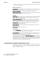
Page 23: ...e the word terminal or the abbreviation VSAT Both refer to the HN9200 satellite modem Screen and page are both used to refer to a set of information from your computer or satellite modem that is displayed on your computer monitor Text links The System Control Center home page includes the following text links System Status links View System Status Opens the System Status page which displays genera...

Page 24: ...settings Contact information Opens to a page that provides contact information for assistance and additional information Restart HN9200 Restarts the satellite modem myHughesNet Note myHughesNet links may or may not be present on your satellite modem depending on the country where the modem is used and your service plan Go to myHughesNet provides access to the HughesNet Web Portal which contains a ...

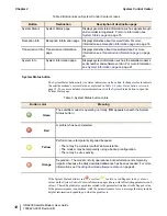
Page 25: ... example the System Status button is a link to the System Status page Click the button to go to the page identified by the label The System Status button link is also a status indicator as explained in Table 3 System Status button colors on page 12 The other three button links are links only they are not indicators Figure 7 System Control Center button links The destination page for each button li...

Page 26: ...see more detailed status information click the System Status button to open the System Status page Table 3 System Status button colors Meaning Button color The satellite modem is operating normally OK appears beneath the System Status button Green A problem has been detected Red Performance is temporarily impaired because Yellow There may be a problem with Web Acceleration The modem may be tempora...

Page 27: ...inks appear in the left panel of each System Control Center page except the home page Note Some of these links may not appear because they are not enabled by the NOC Home Opens the System Control Center home page Problem Troubleshooting Opens the Problem Troubleshooting page a tool that can help you solve common problems you could encounter while using the satellite modem For details see Troublesh...

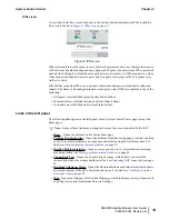
Page 28: ...ontrol Center screens list status and operational parameters and their current values in a tabular format For example the following illustration shows the Reception Information page The left column list the parameters and the right column shows the current value of the parameter listed in the left column Parameters are listed in this format on these screens System Status page Reception Information...

Page 29: ...0 System Information page on page 21 Red flag indicator On the status and information screens a red flag next to a value indicates a problem related to the parameter listed in the same row where the flagged value appears The flagged value appears in the right column the parameter appears in the left column The value indicates the current state of the parameter 15 HN9200 Satellite Modem User Guide ...

Page 30: ...u will not see the screen or screens for that feature or links to it Features that may be enabled or disabled by the NOC are Web Acceleration Problem Troubleshooting Detailed Problem Statistics Port Forwarding Download Allowance Status Browsing Optimization Utility System Status page The System Status page displays important information about the satellite modem s operational status Available syst...

Page 31: ...status Click the displayed TxCode for corresponding Help information Transmit Status Indicates if the satellite modem s software and configuration are up to date Software Download Status Indicates if the modem has been commissioned registered with the system Click the Service History link if you want to see a history of your customer account Service Status Indicates if TCP Acceleration is operatio...

Page 32: ... if the receive data path is operational or other status Click the displayed RxCode for explanation of the displayed code Receive Status Number of data messages received by the satellite modem Frames Received Percentage of received frames determined to be corrupted Any number greater than zero indicates a problem except when adverse Frames with Errors weather conditions are present Frames may be c...

Page 33: ...ational or if there is a problem Normal receive status is indicated by the message Receiver operational RxCode 5 The following two illustrations show how you can view a list of all RxCodes or see an explanation of the currently displayed RxCode Each RxCode except RxCode 5 indicates a specific problem in the receive path Figure 14 Finding additional Receive Status information The next illustration ...

Page 34: ...ns Number of frames that could not be sent A continuously increasing value indicates a transmission problem If a low value is displayed Number of Failed Transmissions and does not increase and the system is functioning there is no reason for concern Total number of data packets queued for transmission to the satellite since the modem was last restarted Number of Packets Submitted for Transmission ...

Page 35: ...on Figure 18 List of TxCodes not all codes are shown System Information page The System Information page shown in Figure 19 System Information page on page 22 provides system information for the satellite modem such as Site ID and the release number of the modem s operational software 21 HN9200 Satellite Modem User Guide 1038623 0001 Revision B Chapter 2 System Control Center ...

Page 36: ...of the System Information page are explained in the following table Other sections of the screen Transmit Radio Info and Satellite provide additional information about the modem installation and the modem software Software Configuration Table 7 System Information page parameters HN9200 Info section Explanation Parameter Identifies the site where the modem is installed Site ID The modem s serial nu...

Page 37: ...AT translates this address to local private addresses in the range NAT IP Address 192 168 0 x that can be used by the devices on your local network where x 0 9 The NAT subnet mask range of available addresses assigned to the modem is always 255 255 255 255 NAT Subnet mask Port Forwarding Configuration page Note The Port Forwarding Configuration page and link are present on your HN9200 only if they...

Page 38: ... only if they have been enabled by the NOC Whether they are enabled or not depends on your service plan To ensure fair Internet access for all HughesNet subscribers some HughesNet subscriber service plans include a limit on how much information can be downloaded daily If a subscriber exceeds the download limit the modem s browsing and download speed is temporarily reduced To view your download all...

Page 39: ...nformation about download allowance go to this Web site http legal hughesnet com Help page The System Control Center Help page Figure 23 Help page on page 26 contains information to help you get started in using the satellite modem find contact information for assistance and other helpful information Review the Help page information to become familiar with the modem To display the Help page Click ...

Page 40: ...nter tools for troubleshooting The System Control Center includes screens that are useful for troubleshooting For details see Troubleshooting common problems on page 33 Confirming NOC connectivity on page 39 Viewing problem related statistics on page 49 HN9200 Satellite Modem User Guide 26 1038623 0001 Revision B System Control Center Chapter 2 ...

Page 41: ...anel and small LEDs on the LAN port on the back of the modem The LEDs provide information about the satellite modem s operating status Topics Front panel LEDs LAN port LEDs Using LEDs for troubleshooting 27 HN9200 Satellite Modem User Guide 1038623 0001 Revision B ...

Page 42: ...off briefly Flashing means the LED alternates between on and off for periods of sec to 1 sec Table 8 Front panel LED indications Satellite modem status Appearance LED Satellite modem is connected to a computer network card or Ethernet device On LAN Transmitting and or receiving data Blinking No device is connected to the LAN port or the device connected to the LAN port is not working properly Off ...

Page 43: ...ting or receiving data Indicates an operational problem If it appears the LEDs are not functioning properly make sure you have the correct power supply Refer to Checking the power supply on page 52 for detailed power supply information LAN port LEDs Green and orange LEDs on the LAN Ethernet port on the modem s rear panel indicate link status and speed as explained in Figure 25 LAN port LEDs on pag...

Page 44: ......

Page 45: ...eshooting information are listed below Using the front panel LEDs for troubleshooting For explanation of red flags on System Control Center screens see Red flag indicator on page 15 Problem with a connected device Improper settings on the computer connected to the satellite modem can cause problems For instructions on configuring a computer to work properly with the modem see Computer settings on ...

Page 46: ...ply disconnect the AC power cord from the power source power strip wall outlet or surge protector If the satellite modem uses a DC DC power supply disconnect the DC input cable connector from the modem s power supply In either case AC DC or DC DC do not unplug the power cord from the satellite modem s rear panel Doing so could result in static electricity discharge that could shock you and or dama...

Page 47: ...e modem Follow these steps to use the Problem Troubleshooting page to diagnose and correct a problem 1 Click the Problem Troubleshooting link in the left panel of any System Control Center page except on the System Control Center home page the Problem Troubleshooting link is located below the DIAGNOSTIC UTILITIES heading The Problem Troubleshooting page opens Figure 27 Problem Troubleshooting page...

Page 48: ...lem contact your service provider Cannot access the Internet If you can access the System Control Center but you cannot access the Internet you may be able to resolve the problem by performing some or all of the following troubleshooting procedures Confirming that the satellite modem is commissioned on page 35 Confirming the receive signal on page 36 Confirming the transmit signal on page 36 Confi...

Page 49: ...r com or 192 168 0 1 3 Press Enter The System Control Center home page opens Confirming that the satellite modem is commissioned To confirm that the modem is commissioned 1 At the System Control Center click the System Info link The System Information page appears Figure 28 System Info page Note The System Info page for your installation may show different fields and values 2 In the HN9200 section...

Page 50: ...s Click the RxCode for explanation of the problem and or troubleshooting information Figure 29 Reception Info page Note The RxCode shown is an example Confirming the transmit signal To confirm that the modem is properly transmitting signals to the satellite 1 At the System Control Center click the Transmission Info link The Transmission Information page appears 2 In the Transmit Status field check...

Page 51: ...m Status page appears Figure 31 Confirming that TCP Acceleration is operational 2 Check the TCP Acceleration Status field If the TCP Acceleration Status is Operational TCP Acceleration is enabled and working properly Proceed to Confirming that Web Acceleration is operational on page 38 3 If the TCP Acceleration Status is Disabled restart the modem a Go to the System Control Center home page b In t...

Page 52: ...eleration is operational Note This section applies only if the NOC operator has enabled Web Acceleration on the satellite modem Web Acceleration is a Hughes feature that enhances browsing performance on non secure web sites Follow these steps to confirm that Web Acceleration is operating properly 1 From any System Control Center page observe the System Status button indicator If the indicator butt...

Page 53: ...ord from the modem s rear panel Doing so could result in static electricity discharge that could shock you and or damage the modem 7 Check the Web Acceleration Status field again If Web Acceleration is still not operational contact your service provider for assistance Confirming NOC connectivity Use the Connectivity Test page to check connectivity to the Hughes Network Operations Center NOC You ma...

Page 54: ...dress This section applies only if the modem is using a static IP address If pinging the modem address fails and DHCP is disabled on the modem the default gateway address is probably not set correctly in the computer s operating system settings The default gateway address should be the modem IP address as displayed on the System Information page HN9200 Info section in the LAN1 IP Address field 1 C...

Page 55: ...ovided by the customer b Press Enter If the ping test succeeds there may be a temporary problem with the web site you originally tried to access Wait a while and then try to access the web site again If the ping test fails continue with these steps 3 Ping the test server a Type ping 198 77 116 39 b Press Enter If the ping test is successful but you still cannot browse the Internet complete the pro...

Page 56: ...ected to an Ethernet device Satellite modem connected directly to a computer Follow the steps below if the modem is connected directly to a computer 1 On the computer desktop double click the System Control Center shortcut icon 2 If the System Control Center does not appear open a web browser 3 Type www systemcontrolcenter com in the browser s address bar 4 Press Enter 5 If the System Control Cent...

Page 57: ...l cannot access the System Control Center contact your service provider If you can now access the System Control Center your Ethernet device may not be properly configured Refer to the documentation for your Ethernet device to configure it properly Be sure to re connect the satellite modem to the Ethernet device before attempting to access the System Control Center Using the front panel LEDs for t...

Page 58: ...power cord from the modem s rear panel Doing so could result in an electrical shock or damage to the modem The modem may recover 2 If the fatal error indication continues the modem must be replaced Contact your service provider All LEDs flashing If all LEDs are flashing simultaneously this indicates that the satellite modem s firmware is corrupted A modem in this state cannot be recovered Contact ...

Page 59: ...d back into the power source e If the power source is DC plug the input cable back into the power supply Do not power cycle the satellite modem by unplugging the power cord from the modem s rear panel Doing so could result in static electricity discharge that could shock you and or damage the modem 3 If the LAN LED is still off check the LAN port LEDs on the back panel If the Orange LED is on and ...

Page 60: ... device documentation 8 If the LAN LED is still off restart the computer 9 If the LAN LED is still off try connecting the satellite modem to another computer If the front panel LAN LED is now on there may be a problem with the computer that was connected to the satellite modem If the LAN LED is still off contact your service provider Problem with a connected device If a device other than a compute...

Page 61: ...upply c Wait 10 sec d Plug the power cord back into the power source e If the power source is DC plug the input cable back into the power supply Do not power cycle the satellite modem by unplugging the power cord from the modem s rear panel Doing so could result in static electricity discharge that could shock you and or damage the modem 4 If the problem persists contact your service provider Syst...

Page 62: ...the problem 3 If the equipment seems to be OK power cycle the satellite modem a Unplug the power cord from the power source b If the modem is connected to a DC power source unplug the DC input cable from the satellite modem s power supply c Wait 10 sec d Plug the power cord back into the power source e If the power source is DC plug the input cable back into the power supply To remove power from t...

Page 63: ...ms could develop later Therefore correct operation of the modem is not an indication that the cables are adequately tightened 5 Reapply power to the modem by plugging the power supply back into the surge protector or AC outlet A suitable surge protector is recommended to protect the satellite modem from possible damage due to power surges 6 Wait 5 min 7 Check the connector to see if it is hot If t...

Page 64: ... or in the left panel of other System Control Center pages The Detailed Problem Statistics page appears Figure 34 Detailed Problem Statistics 2 From the drop down list above the Get Statistics button select a category of statistics for example TCP Acceleration If a service provider representative is assisting you the representative will tell you which statistics to select HN9200 Satellite Modem Us...

Page 65: ...s strong enough the modem may stop receiving signals from the satellite and stop transmitting If this happens the Transmit and Receive LEDs both turn off Antenna reception may be degraded by heavy rain or snow or by a buildup of moisture snow or ice on the antenna Similar conditions at the NOC can interfere with signals for brief periods of time Signal strength is restored when rain or snow subsid...

Page 66: ...possible damage due to power surges Observe the power standards and requirements of the country where it is installed If the LEDs do not function properly as described in this chapter check the label on the power supply and verify that you have the correct power supply For an AC DC power supply the Hughes part number on the power supply should be one of the following 1500089 0001 1500185 0001 If t...

Page 67: ...that can be used on the Internet Both private and public addresses can be dynamic or static Both the modem and a connected computer can have either type of address dynamic or static The type used depends on requirements a customer might have and their service plan A static IP address or addresses are available only if they are specified in the service plan Typically home users use a private IP add...

Page 68: ...trolcenter com and press Enter The System Control Center home page appears 4 Click the System Info button near the top of the page The System Information page appears 5 In the Software Configuration section observe the value in the DHCP field If DHCP is enabled on the satellite modem you must configure the computer to support DHCP Then the computer uses a dynamic address that is automatically assi...

Page 69: ... 55 Note Depending on the computer s security settings a message may appear requesting that you confirm the action before proceeding If you see this message click Continue to proceed Figure 37 Local Area Connection Properties Windows 7 5 Ensure that both Client for Microsoft Networks and Internet Protocol TCP IP are installed and checked as shown 6 If NetBEUI is installed and checked uncheck it or...

Page 70: ...line that starts with IPv4 Address or IPv6 Address Configuring Windows Vista to use DHCP 1 From the Windows desktop select Start Settings Network Connections A list of network adapters appears as shown in Figure 36 Network and Sharing Center Windows 7 on page 56 The Local Area Connection NIC Card icon must appear under the LAN or High Speed Internet heading If it does not the network is not instal...

Page 71: ...tion Properties Windows Vista 3 Ensure that both Client for Microsoft Networks and Internet Protocol TCP IP are installed and checked as shown 4 If NetBEUI is installed and checked uncheck it or uninstall it 5 Highlight the appropriate TCP IP connection Be careful not to uncheck the checkbox 6 Click Properties The Internet Protocol Properties dialog appears as shown in Figure 41 Internet Protocol ...

Page 72: ...nnections Windows XP on page 58 A Local Area Connection icon must appear under the LAN or High Speed Internet heading If it does not the network is not installed correctly Figure 42 Network connections Windows XP Note If a red X appears next to the Local Area Connection icon check your connections You cannot successfully configure your system if the red X is present 3 Right click the Local Area Co...

Page 73: ...s shown in Figure 44 Internet Protocol Properties Windows XP on page 59 Figure 44 Internet Protocol Properties Windows XP 8 On the General tab ensure that both the Obtain an IP address automatically and Obtain DNS server address automatically options are selected If not select them 9 Click OK 10 Confirm that you have an IP address a Click Start Run b Type cmd and click OK c Type ipconfig renew and...

Page 74: ... Select Using DHCP from the configure drop down list on page 60 The IP Address field becomes disabled Figure 46 Select Using DHCP from the configure drop down list 5 Click Apply Now to close the screen Configuring a computer to use a static IP address If it is desired or necessary for a computer to have a fixed or permanent static IP address the computer should be configured for a static IP addres...

Page 75: ...n icon indicated by the arrow in Figure 47 Network and Sharing Center Windows 7 on page 61 If you do not see a Local Area Connection link or if a red X appears next to the link the network is not installed correctly Check your network configuration and connections You cannot configure your system if the red X is present Figure 47 Network and Sharing Center Windows 7 3 Click the Local Area Connecti...

Page 76: ...9 Internet Protocol Properties Windows 7 on page 62 Figure 49 Internet Protocol Properties Windows 7 9 On the General tab select Use the following IP address 10 Enter the IP address and subnet mask in the appropriate fields If you do not know what static IP address or range of addresses is available for use see Understanding the modem address and computer address on page 53 11 Select Use the follo...

Page 77: ... satellite modem network connection and select Properties The Local Area Connection NIC Card Properties dialog appears as shown in Figure 51 Local Area Connection Properties Windows Vista on page 63 Note Depending on your security settings a User Account Control message may appear requesting that you confirm the action before proceeding If you see this message click Continue to proceed Figure 51 L...

Page 78: ...he Preferred DNS server field 11 Click OK 12 Restart the computer Configuring Windows XP to use a static IP address 1 From the Windows desktop select Start Settings Control Panel 2 Double click the Network Connections icon in the Control Panel window A list of network adapters appears A Local Area Connection icon must appear under the LAN or High Speed Internet heading If it does not the network i...

Page 79: ...Connection properties dialog as shown in Figure 54 Local Area Connection Properties Dialog Windows XP on page 65 Figure 54 Local Area Connection Properties Dialog Windows XP 5 If NetBEUI is installed and checked uncheck it or uninstall it 6 Highlight Internet Protocol TCP IP Be careful not to uncheck the checkbox 7 Click Properties The Internet Protocol Properties dialog appears as shown in Figure...

Page 80: ...uter address on page 53 10 Select Use the following DNS server addresses 11 Enter 66 82 4 8 in the Preferred DNS server field 12 Click OK 13 Restart the computer Configuring a Mac computer to use a static IP address 1 From the Mac interface select System Preferences The System Preferences menu appears 2 Under Internet Network click the Network icon The Network screen appears as shown in Figure 56 ...

Page 81: ...standing the modem address and computer address on page 53 6 Click Apply Now to close the screen and complete the configuration Configuring proxy settings If your web browser cannot connect to the Internet check the browser s proxy settings If the browser is configured for the computer to use a proxy server to connect to the Internet try changing the setting to not use a proxy server These steps e...

Page 82: ... Figure 58 LAN settings Internet Explorer 4 Uncheck the checkbox next to Use a proxy server for your LAN 5 Click OK 6 Close Internet Explorer and re launch it to make sure the changes take effect HN9200 Satellite Modem User Guide 68 1038623 0001 Revision B Computer settings Appendix A ...

Page 83: ...ltiple users may result in speed degradation Speed and uninterrupted use of service are not guaranteed Actual speeds may vary If you connect your satellite modem to a LAN you must Install and configure an Ethernet hub modem or wireless network base station Install and configure a NIC in each computer to be connected The NICs must be set to auto negotiate Refer to the manufacturer s installation in...

Page 84: ...rnet wired network basics You can purchase an Ethernet hub cables and NICs at most computer supply stores This equipment is relatively inexpensive and easy to install When selecting an Ethernet hub consider the number of computers you intend to connect to the network and how fast you need or want the data connection to be If the users on your network share large files you may need a faster hub a s...

Page 85: ...be purchased at an electronics computer or home supply store If you feel unsure about installing Ethernet cable contact a professional installer Run Ethernet cables behind walls whenever possible or secure them to floor baseboards and doorway frames Do not use staples to secure Ethernet cable Leave enough slack in the cable to accommodate possible future repair splices or moving of equipment 71 HN...

Page 86: ......

Page 87: ...ications network protective operational and safety requirements The Department does not guarantee that the equipment will operate to the user s satisfaction Before installing the equipment users should make sure they are permitted to connect to the facilities of the local telecommunications company The equipment must also be installed using an acceptable method of connection In some cases the comp...

Page 88: ... required to take adequate measures FCC Part 15 This section applies to the HN9200 satellite modem Standards to which conformity is declared FCC Part 15 The modem complies with Part 15 of the FCC Rules Operation is subject to the following two conditions 1 This device may not cause harmful interference and 2 this device must accept any interference received including interference that may cause un...

Page 89: ...adio interference in which case the user may be required to take adequate measures R TTE EU This product is within the scope of the EU Radio Equipment and Telecommunications Terminal Equipment R TTE Directive IPoS The Hughes HN9200 system is compliant with IPoS ratified by the Telecommunications Industry Association TIA 1008 first published in October 2003 and issued as Revision A in May 2006 Figu...

Page 90: ......

Page 91: ...fer Protocol HTTP Interference Causing Equipment Standard ICES Identifier ID Indoor unit satellite modem IDU Internet Protocol IP Internet Protocol security IPSec Internet service provider ISP A Hughes proprietary routing protocol ISRP Local area network LAN Light emitting diode LED Limited Liability Company LLC Network address translation NAT Extended User Interface network transfer protocol NetB...

Page 92: ...trol Protocol TCP User Datagram Protocol UDP Underwriters Laboratory UL Uniform resource locator URL Volts alternating current VAC Value added reseller VAR Volts alternating current VDC Very small aperture terminal VSAT Zone improvement plan U S Postal Service ZIP HN9200 Satellite Modem User Guide 78 1038623 0001 Revision B Acronyms used in this guide Appendix D ...

Page 93: ...tailed Problem Statistics page 49 DHCP settings 53 54 DNS setting 41 Download allowance status 13 24 Download limit 18 24 Download speed 24 E EMC standards 75 EMI standards 74 Environment 3 Ethernet network basic information 70 F Fair Access Policy 18 See also Download limit FCC Part 15 74 Firewall 42 Front panel LEDs 28 H Help page System Control Center 25 Home networking 69 I IP address 23 53 60...

Page 94: ...ning 8 System Control Center continued Reception Information page 18 Shortcut for System Control Center 8 System Information page 21 System Status button colors 12 System Status page 16 Transmission Information page 20 System Information page 21 System Status button colors 12 System Status page 16 T Tests and testing See Troubleshooting Transmission Information page 20 Transmit status 20 Troublesh...

Reviews: