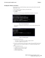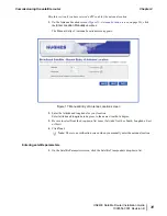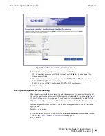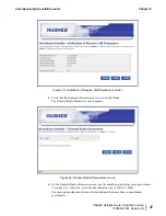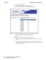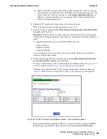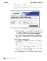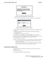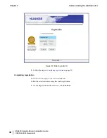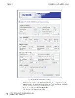
Figure 26: Verification of Transmit Radio Parameters screen
6.
Verify that the displayed information is correct and click
Next
.
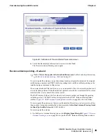
The Receive Antenna Pointing screen opens.
Receive antenna pointing – Ka-band
Note: This section applies to Ka-band installations only.
For Ku-band, skip this section;
go to
Receive antenna pointing – Ku-band
on page 43.
To receive-point the antenna, you go the antenna location and point the antenna at its assigned
satellite using a squinter and DAPT (both are pointing tools) and then validate pointing on the
installer laptop as explained in this section.
The squinter blocks half the feed horn so you can measure Es/No at two azimuth positions and
at two elevation positions. When the antenna is pointed correctly, the two azimuth Es/No values
match, and the two elevation Es/No values match.
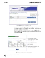
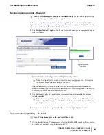
The DAPT displays SQF and Es/No values in real time and guides you through the pointing
validation process. The DAPT values are replicated on the DAPT Antenna Pointing Status
window (
Figure 28: DAPT Antenna Pointing Status window
on page 40), also in real time.
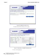
To receive-point the antenna, use the screens illustrated in this section,
and you must also follow
the procedure for squinter pointing that is documented in the
Ka-Band Antenna Pointing Guide
for Bent-Pipe Satellite Networks
(1038764-0001).
To receive-point the antenna:
1.
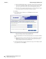
On the Receive Antenna Pointing screen, click
Display Signal Strength
(
on page 40) to open the DAPT Antenna Pointing Status window.
39
HN9400 Satellite Router Installation Guide
1038554-0001 Revision B
Chapter 4
Commissioning the satellite router
Summary of Contents for HN9400
Page 1: ...1038554 0001 Revision B March 2 2011 HN9400 Satellite Router Installation Guide ...
Page 10: ......
Page 16: ......
Page 26: ......
Page 34: ......
Page 68: ......
Page 74: ......
Page 92: ......
Page 120: ......
Page 124: ......
Page 128: ......
Page 134: ...HN9400 Satellite Router Installation Guide 122 1038554 0001 Revision B Index ...

