background image

9

DXJR/DKPH*PE+

Art. Nr.: 577460

Stand 08/2010

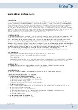
1. POSITION

It is recommended to place the pump of the counter-current in a way that the connection between the pump and the fitting parts 
is as short as possible. In any case you have to ensure that the pump is installed in a manner that the axle is in a horizontal position. 
Changing the place of the pump is possible due to construction reasons. We recommend not to go beyond 5 m maximum distance 
for avoiding any higher flow reduction on the suction side. While placing the installation please ensure that the pipes in that 
maximum area are passed without breakes and in a horizontal way. If there are larger distances, you have to increase the diametre of 
the pipes. The place of the pump has to be an area, where the ambient temperature does not exeed 40°C. Place the pump under the
water level because the pump does not suck itself. The pump and the locking parts have to be accessible any time.
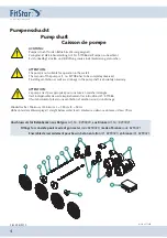
Ventilation and drainage as well as floor drain have to be provided in the pump shaft.

2. INSTALLATION

The equipment is delivered serially with complete wall built-in and fitting parts. The housing pressure side has to be installed in a way 
that the center of the injection nozzles is 200-250 mm under the water level and that the minimum distance to the side wall is  
1.5 m. The distance of the injection nozzles to each other is 200 mm. The boreholes for the housings into the pool barrier can be 
made without any problem with the included drilling template. Please follow the instructions on the drilling template. 
The housing suction side should be installed in a way that the centre of the housing is 800 mm under the water level. The distance 
between the suction housings to each other should be 2 m. The boreholes for the housings into the pool barrier can be made without 
any problem with the included drilling template. After finishing of the construction and cleaning the fitting parts you can assembly 
the injection nozzles and the suction sieves. Fix the suction sieves with the screws delivered at the fitting part suction side.
Screw the injection nozzles in the fitting parts pressure side. After that, install the air inlet in the pump shaft.
The return-valve has to be fixed over the water level. The connection between the pump and the fitting parts is made on site.

3. STARTING UP

Ensure that the pool is full of water before starting up the pump. Avoid any dry run of the pump.
1. 

Open both valves and turn on the installation by using the sensor switch.

2.  

Check air injection.

3.  

Hose and tube connections have to be checked on leakage during the working process. Due to temperature differences tighting  


of the connections can get neccessary. (Check the system on leakage by reducing the installation as much as possible).

4. OPERATING

The installation is switched on or off by pushing the sensor switch. The direction of the injection nozzles is adjustable.
The water jet should be set up in a way that the swimmer swims against whole jet.

5. HIBERNATION

The pump has to be empty. Close both valves and open the screw on the housing of the pump for emptying.

6. POSSIBLE PROBLEMS AND SOLUTIONS

6-1.  Installation does not produce sufficient power:


Pump is turning in the wrong direction. Water level is too low.


Pump sucks in air. Valve is not completly open. Suction pipe leaks. 


Pump is clogged (with leaves for instance).


If the causes can not be identified, inform the service responsible.

6-2.   Pump can not be switched on:


Check the cable between the sensor switch and the control and check the configuration of the connection of the control.

6-3.   Relay for motor protection switches off:


Relay for motor protection is not adjusted correctly.  


Rated current and local situations have to be consistent with the adjustment of the relay for motor protection.  


Pump is overheated. Cool down the motor and start it again. 


Phase failed - check the fuses.

6-4.   Residual Current Device (RCD) switches off:


The equipment has to be checked by an electrician.

Installation instructions

Summary of Contents for 8290020

Page 1: ...PE FITSTAR Gegenschwimmanlage X Stream für Betonbecken FITSTAR counter current system X Stream for concrete pools FITSTAR nage à contre courant X Stream pour bassin carrelé Stand 08 2010 Art Nr 577460 D EUDQG RI XJR DKPH PE ...

Page 2: ... values is a controlled movement circuit ATTENTION Les attractions aquatiques peuvent lors d un arrêt prolongé avoir une contamination d eau stagnante dans les tuyauteries Cette possibilité peut provoquer une contamination bactérielle résiduelle dans le volume du bassin lors de la remise en service Afin de remédier à cet effet et de respecter les normes d hygiène nous recommandons d installer sur ...

Page 3: ... Wasserspiegel liegen Bei Schwimmbadabdeckungen müssen Abweiser an den Gegenschwimmanlagen montiert sein weil sonst der Sensorschalter durch Gegenschlagen der Schwimmbadabdeckung ausgelöst wird Die Verrohrung wird bauseits erstellt ATTENTION All metal mounting parts have to be crossbonded and earthed closed potential circuit according to German VDE 0100 part 702 The non return valve must be instal...

Page 4: ...inage in the pump shaft is absolutely necessary ATTENTION La pompe n est pas appropriée pour une mise en marche immergée Il est indispensable de suivre impérativement les instructions réf 577086 Il faut absolument prévoir une ventilation et aération ainsi qu un drainage Anschlusssatz für Betonbecken aus Rotguss Art Nr 8290020 aus Bronze Art Nr 8290021 Fittings for concrete pools made of gun metal ...

Page 5: ... nozzle embout de tuyau 5 4 500508 Schlauchschelle hose clip collier 6 2 510580 Schlauch NW 19 hose Ø19 tuyau Ø19 7 2 8675050 Rückschlagventil return valve clapet anti retour Anschlusselemente fitting kit kit de raccordement Art Nr code réf 8290050 8 2 7388050 Übergangsnippel junction fitting reducteur G2 AG G2 IG 9 4 7184050 Schieber valve vanne papillon G2 10 2 7158550 Pumpendruckstutzen pump pr...

Page 6: ...d zu messen Das Motorschutzrelais ist auf den Nennstrom des Motors einzustellen Eine Funktionsprüfung ist unbedingt erforderlich ACHTUNG Die Vorschriften des VDE und des örtlichen EVU Elektrizitäts Versorgungs Unternehmen sind bei der Installation der Anlage unbedingt zu beachten Installation nur durch einen beim örtlichen EVU zugelassenen Elektro Installateur nach VDE 0100 Teil 702 und 430 ausfüh...

Page 7: ... 2 5 mm d une protection primaire avec un fusible de 3x16 A T et d un disjoncteur différentiel de perte 0 30 mA est nécessaire pour la station de nage à contre courant cette protection supplémentaire suivant la norme C 1500 VDE 010013 N doit être installée Le câble d alimentation de la commande à la pompe est 4 x2 5 mm Mise en place d un interrupteur optique La distance maximum de la commande au b...

Page 8: ... Nach Fertigstellung der Bauarbeiten und säubern der Einbau teile werden die Einstrahldüsen und die Ansaugsiebe montiert Die Ansaugsiebe mittels der mitgelieferten Schrauben am Einbauteil Saugseite befestigen Die Einstrahldüsen in die Einbauteile Druckseite einschrauben Im Pumpenschacht wird anschließend die Luftansaugung angebracht Das Rückschlagventil muss über dem Wasserspiegel befestigt werden...

Page 9: ...onstruction and cleaning the fitting parts you can assembly the injection nozzles and the suction sieves Fix the suction sieves with the screws delivered at the fitting part suction side Screw the injection nozzles in the fitting parts pressure side After that install the air inlet in the pump shaft The return valve has to be fixed over the water level The connection between the pump and the fitti...

Page 10: ...eller Après finition du gros oeuvre et nettoyage des pièces à sceller les injecteurs de buse et crépine sont à installer Les crépines sont à fixer sur les pièces à sceller aspira tion à l aide des vis faisant partie de la livraison les injections suivant le même système que les crépines Dans le local de pompe les aspirations d air sont à raccorder la vanne anti retour est à fixer au dessus du nive...

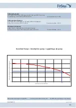
Page 11: ...0 Hz Power consumption 3 4 KW Données techniques Le débit effectif est dépendant de la distance de la pompe Puissance de la pompe 2 6 KW Tri phasés 230 400 Volts 50 Hz Puissance absorbée 3 4 KW Art Nr 577460 Stand 08 2010 Kennlinie Pumpe identity line pump signalétique de pomp Technische Änderungen vorbehalten Technical amendments reserved Modifivations techniques sous réserves 0 00 5 00 10 00 15 ...

Page 12: ...D EUDQG RI XJR DKPH PE Perfektion in jedem Element Kahlenbecker Straße 2 58256 Ennepetal Germany Telefon 49 0 23 33 96 96 0 Telefax 49 0 23 33 96 96 46 E Mail info lahme de Internet www lahme de HUGO LAHME ...

Reviews: