background image

Huisen Furniture (Longnan) Co.,Ltd.

                 Made in China

Please Recycle

THIS INSTRUCTION BOOKLET CONTAINS 

IMPORTANT

 SAFETY INFORMATION. PLEASE READ AND KEEP FOR FUTURE REFERENCE.

Recommended number of people needed for assembly:1

(however it is always better to have an extra hand.)
Estimated assembly time is 1.0 hour

DO NOT RETURN PRODUCT TO THE STORE Individual stores do not stock parts.

___________

____/____/____

 Date Of Purchase

Lot Number

If a part is missing or damaged, call our toll-free customer service line. We will
gladly ship your replacement parts FREE of charge.

1-800-729-1569

For prompt, reliable service please have your assembly manual ready.

Need Parts or Assistance?

Call our toll free number for any assistance

you need 1-800-729-1569

Clean the product with your favorite

furniture polish and a soft cloth. DO NOT

USE harsh chemicals or abrasive cleaners,

Move your new furniture carefully with

two people. Lift and carry the unit,

Never push or drag the unit.

Do not allow children to climb or play on

the unit.

Failure to comply could result in severe
injury.

This unit has been designed to support the

maximum loads shown. Exceeding these
load limits could cause unit sagging,
instability,product collapse and / or serious
injury.

Additional parts are available for a nominal
fee.

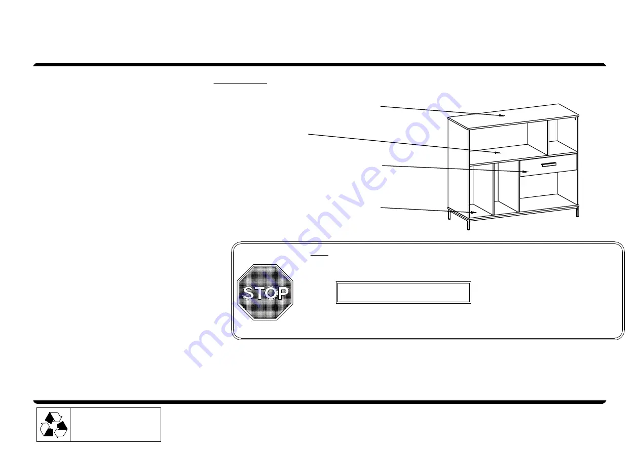
BOTTOM PANEL
MAX LOAD

25 lbs (11.4 kg)

DRAWER BOTTOM PANEL
MAX LOAD

15 lbs (6.8 kg)

MIDDLE SHELF
MAX LOAD

25 lbs (11.4 kg)

TOP PANEL

MAX LOAD

100 lbs (45.5 kg)

MAINSTAYS MULTI COMPARTMENT STORAGE BUFFET

VENDOR STOCK #

MS18-D1-1009-18 Rustic Brown

Summary of Contents for MS18-D1-1009-18

Page 1: ...or Assistance Call our toll free number for any assistance you need 1 800 729 1569 Clean the product with your favorite furniture polish and a soft cloth DO NOT USE harsh chemicals or abrasive cleaners Move your new furniture carefully with two people Lift and carry the unit Never push or drag the unit Do not allow children to climb or play on the unit Failure to comply could result in severe inju...

Page 2: ...cially on carpet Additional parts are available for a nominal fee Read each step carefully before starting It is very important that each step of instruction is performed in the correct order If these steps are not followed in sequence assembly difficulties will occur Make sure all parts are included Most board parts are labeled or stamped on the raw edge Work in spacious area preferably on a carp...

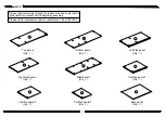
Page 3: ... Qty 1 Middle shelf Qty 1 Partition board 2 Qty 1 Please read completely through the instructions and verify that all parts listed are present before beginning assembly Right side panel Qty 1 3 Partition board 1 Qty 1 Left side panel Qty 1 Partition board 3 Qty 1 Back panel Qty 1 A B C D E F G H I ...

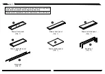
Page 4: ...1 800 729 1569 Drawer back panel Qty 1 Drawer left side panel Qty 1 Metal feet Qty 2 Please read completely through the instructions and verify that all parts listed are present before beginning assembly Drawer bottom panel Qty 1 4 Metal tube Qty 2 Drawer right side panel Qty 1 J K L M ...

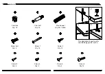
Page 5: ...he cam fastening system works 5 1 4 2 2 1 4 3 Hardware Screw bolt Qty 4 3 6 Cam lock Qty 14 Cam bolt Qty 14 Wood dowel Qty 24 1 Extra Screw 2 Qty 12 5 9 7 8 Screw 3 Qty 4 Screw 5 Qty 2 Screw 4 Qty 2 Screw 6 Qty 14 10 Screw 1 Qty 14 ...

Page 6: ...ey Qty 1 12 16 This illustration shows how the cam fastening system works 11 Drawer slide 1 Qty 1 Drawer slide 3 Qty 1 2 1 4 3 Hardware Drawer slide 4 Qty 1 Drawer slide 2 Qty 1 Handle Qty 1 6 13 15 14 17 18 Safety strap kit Qty 1 19d 19 19a 19b 19c 19e ...

Page 7: ... BOTTOM OF THE CAM BOLT THE LARGER RING ABOVE THE 3 THREADS SHOULD REST ON THE PANEL This illustration shows how the CAM fastening system works 1 2 3 4 5 6 2 4 Position the CAM LOCK so the opening is facing the outer raw edge of the shelf When connecting the side panels to the shelves the CAM LOCK is turned approximately way clockwise to secure the bolt Failure to properly lock the CAM LOCK could ...

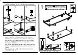
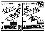
Page 8: ...E F as shown 6 2 6 3 x 3 x 3 2 2 2 2 6 6 6 6 6 1 3 6 2 2 2 x 1 Drawer slide 2 x 1 Drawer slide 1 Insert hardware into part C D as shown 15 15 16 1 3 3 3 3 3 3 3 3 1 1 1 1 16 3 3 3 3 3 3 1 1 1 1 1 1 Screw 2 Screw 2 approx 3 8 3 Cam bolt 2 x 4 Cam bolt 2 x 4 The arrow point to the hole 1 2 3 6 16 1 2 3 6 15 3 3 ...

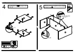
Page 9: ...owel x 4 Cam lock E C D 3 3 3 3 LOCK AFTER TAP 3 1 1 1 1 1 approx 3 8 3 x 4 Insert hardware into part G H as shown Attach part C D to part E and then tighten the cam locks 1 3 1 3 3 3 3 1 all unfinished edges are facing UP ...

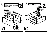
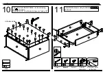
Page 10: ...F B G H D C E D E C F G H 5 x 8 Screw 1 Attach part H to part E using screw as shown Attach part F G to part E and then tighten the cam locks 5 x 2 Screw 1 5 5 5 5 1 all unfinished edges are facing UP all unfinished edges are facing UP LOCK AFTER TAP x 4 1 5 5 5 5 5 5 5 ...

Page 11: ... part B using screw as shown x 14 Screw 6 C H D E F G B LOCK AFTER TAP x 6 C H D E F G B Attach part A to the structure and then tighten the cam locks as shown 9 10 10 10 10 10 10 10 10 10 10 10 10 10 A 1 1 all unfinished edges are facing UP P O ...

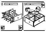
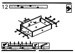
Page 12: ...lign and attach BACK PANEL I to the unit using nail as shown PLEASE NOTE All unfinished edges are facing UP Plastic connector x 2 x 26 11 12 12 12 The arrow point to the hole Unfinished side Assemble the drawer using hardware as shown 11 37 11 11 11 11 11 11 11 11 11 11 11 11 11 11 11 11 11 11 11 11 5 7 8 12 ...

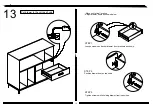
Page 13: ... 6 17 x 1 Drawer slide 3 18 x 1 Drawer slide 4 x 1 Handle 13 Screw 2 6 12 Attach handle to part J using screw as shown Attach drawer slides to part M L using screw as shown 13 37 K N M L J 9 9 6 6 6 6 6 18 17 13 9 6 17 18 ...

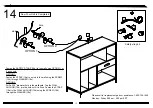
Page 14: ...wn 14 STEP 3 Tighten screws while holding drawer front in position STEP 2 Position drawer front as required STEP 1 Loosen screws on back of drawer front brackets as shown Move unit to final location Adjust drawer fronts as shown below ...

Page 15: ...ll using the SCREW 19d through WASHER 19e OPTION 2 Drill a 3 16 diameter hole in the wallboard Tap the WALL ANCHOR 19b into the hole until it is flush Fasten the STRAP 19a to the WALL ANCHOR 19b using the SCREW 19d through the WASHER 19e 19a 19e 19d 19b 19a 19d 19e 19a 19c 19e 19a 19e 19d 19c 19b 19 Please call for replacement parts or assistance 1 800 729 1569 Monday Friday 9 00 am 5 00 pm EST ...

Page 16: ...NEL INFERIOR DEL CAJÓN CARGA MÁXIMA 15 lb 6 8 kg ESTANTE DEL MEDIO CARGA MÁXIMA 25 lb 11 4 kg PANEL SUPERIOR CARGA MÁXIMA 100 lb 45 5 kg MAINSTAYS APARADOR DE ALMACENAMIENTO MULTI COMPARTIBLE EL STOCK DE VENDEDOR Huisen Furniture Longnan Co Ltd Hecho en China Por Favor De Reciclar ESTE MANUAL DE INSTRUCCIÓN CONTIENE INFORMACIÓN IMPORTANTE DE SEGURIDAD POR FAVOR DE LEER Y GUARDAR PARA FUTURAS REFER...

Page 17: ...illo Mover tu mueble nuevo con cuidado Mejor con dos personas para levanter y llevar la unidad a la nueva Nunca empujar arrastrar tus muebles especialmente sobre la alfombra nominal Leer atentamenta cada paso antes de comenzar Es muy imporpante que cada paso correcto Si no se siguen los pasos en el orden dificultades pueden ocurrir etiquetados o estampado en el borde Trabajar en una zona amplia me...

Page 18: ...a de tabique 1 Cantidad 1 Panel lateral izquierdo Cantidad 1 Tabla de tabique 3 Cantidad 1 Panel posterior Cantidad 1 A B C D E F G H I PIEZAS Por favor de leer completamente la instrucción y verificar que todas las piezas mencionadas están presentes antes de comenzar el ensamblaje Por favor de llamar para piezas de reemplazo o ayudas 1 800 729 1569 ...

Page 19: ...antidad 2 Panel inferior del cajón Cantidad 1 4 Tubo de metal Cantidad 2 Panel derecho del cajón Cantidad 1 J K L M PIEZAS Por favor de leer completamente la instrucción y verificar que todas las piezas mencionadas están presentes antes de comenzar el ensamblaje Por favor de llamar para piezas de reemplazo o ayudas 1 800 729 1569 ...

Page 20: ...adura Cantidad 14 Clavija de madera Cantidad 24 1 Extra Tornillo 2 Cantidad 12 5 9 7 8 Tornillo 3 Cantidad 4 Tornillo 5 Cantidad 2 Tornillo 4 Cantidad 2 Tornillo 6 Cantidad 14 10 Tornillo 1 Cantidad 14 Esta ilustración muestra cómo funciona el sistema de fijación de las combaduras Quincalla ...

Page 21: ... del cajón 1 Cantidad 1 Diapositiva del cajón 3 Cantidad 1 2 1 4 3 Diapositiva del cajón 4 Cantidad 1 Diapositiva del cajón 2 Cantidad 1 Mando Cantidad 1 6 13 15 14 17 18 Cinturón Cantidad 1 19d 19 19a 19b 19c 19e Quincalla Esta ilustración muestra cómo funciona el sistema de fijación de las combaduras ...

Page 22: ...ANELES PARA CUBRIR LOS 3 HILOS EN LA PARTE INFERIOR DEL PERNO DE LEVA EL ANILLO MAYOR POR ENCIMA DE LOS 3 HILOS DEBE DESCANSAR SOBRE EL PANEL Coloque el BLOQUEO DE LEVA para que la abertura esté de cara al borde exterior sin acabar del estante Al conectar los paneles laterales a los estantes el BLOQUEO DE LEVA se gira aproximadamente media carrera hacia la derecha para apretar firmemente el perno ...

Page 23: ...6 6 6 6 6 1 3 6 2 2 2 x 1 diapositiva del cajón 2 x 1 Inserte el hardware en la parte C y D como se muestra 15 15 16 1 3 3 3 3 3 3 3 3 1 1 1 1 16 3 3 3 3 3 3 1 1 1 1 1 1 Tornillo 2 aprox 3 8 3 Tornillo de combadura 2 x 4 2 x 4 15 3 3 16 Tornillo de combadura Clavija de madera Cerrojo de combadura Tornillo 2 diapositiva del cajón 1 La fleche apunta al agujero ...

Page 24: ... 4 Inserte el hardware en la parte G y H como se muestra Fije la parte C y D a la parte E y luego apriete las cerraduras de leva 3 3 3 3 1 Clavija de madera Cerrojo de combadura LOCK DESPUÉS DE TAP Todos los bordes no acabado deben seter mirando hacia arriba ...

Page 25: ...a parte H a la parte E con el tornillo como se muestra Fije la parte F y G a la parte E y luego apriete las cerraduras de leva 5 x 2 Tornillo 1 5 5 x 4 1 5 5 5 5 5 5 5 Tornillo 1 LOCK DESPUÉS DE TAP Todos los bordes no acabado deben seter mirando hacia arriba Todos los bordes no acabado deben seter mirando hacia arriba ...

Page 26: ... como se muestra x 14 Tornillo 6 C H D E F G B LOCK DESPUÉS DE TAP x 6 C H D E F G B Fije la parte A a la estructura y luego apriete las cerraduras de leva como se muestra 9 10 10 10 10 10 10 10 10 10 10 10 10 A 1 P O Todos los bordes no acabado deben seter mirando hacia arriba ...

Page 27: ...lavo como se muestra POR FAVOR NOTA Todos los bordes no acabado deben seter mirando hacia arriba Conector de plástico x 2 x 26 11 12 12 12 La fleche apunta al agujero Lado Inacabado Ensamble el cajón con el hardware como se muestra 11 37 11 11 11 11 11 11 11 11 11 11 11 11 11 11 11 11 11 11 11 11 12 Tornillo 1 Tornillo 3 Tornillo 4 ...

Page 28: ...je la mango a la parte J con el tornillo como se muestra Fije la diapositiva del cajón a la parte M y L con el tornillo como se muestra 13 37 K N M L J 9 9 6 6 6 6 6 18 17 13 17 18 diapositiva del cajón 3 diapositiva del cajón 4 Tornillo 5 Tornillo 2 ...

Page 29: ...l frente del cajón en su posición PASO 2 Coloque el frente del cajón según sea necesario PASO 1 Afloje los tornillos en la parte posterior de los soportes delanteros del cajón como se muestra Mueve la unidad a la ubicación final Ajuste los frentes de los cajones como se muestra a continuación ...

Page 30: ...00pm EST Viga Fije el CINTURÓN DE SEGURIDAD 19a a la pared que usa la OPCIÓN 1 o 2 como mostrada OPCIÓN 1 Fije la CORREA 19a a una viga en la pared con el TORNILLO 19d y una ARANDELA 19e OPCIÓN 2 Taladre un agujero de un diametro de 3 16 en la pared Martille el ANCLA DE MURO 19b dentro del agujero hasta que esté al ras de la pared Fije la CORREA 19a a la ANCLA DE MURO 19b con el TORNILLO 19d y una...

Reviews: