1
A
2
2
2
2
2
2
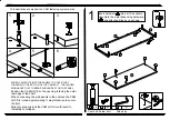
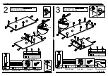
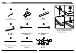
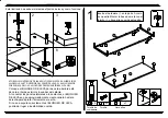
Insert hardware into part A as shown.
Assemble the metal base using hardware
and attached allen key as shown.
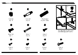
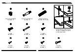
Screw bolt
4
x 4
O
P
Cam bolt
2
x 6
x 1
Allen key
14
7
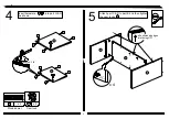
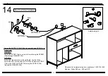
. SCREW CAM BOLTS INTO THE PANELS TO COVER THE 3
THREADS ON THE BOTTOM OF THE CAM BOLT. THE LARGER
RING ABOVE THE 3 THREADS SHOULD REST ON THE PANEL.
This illustration shows how the CAM fastening system works.
1
2
3
4
5
6
2
4
. Position the CAM LOCK so the opening is facing the outer
raw edge of the shelf.
. When connecting the side panels to the shelves, the CAM
LOCK is turned approximately ½ way clockwise to secure
the bolt.
. Failure to properly lock the CAM LOCK could result in
instability or collapse.
4
4
4
4


