background image


Table of Contents 

z


R

Revision History ......................................................................................................... 1 

z


IIntroduction ................................................................................................................ 1 

1. Specifications ................................................................................................................. 2 

1.1. AC adapter (Japan's specifications) ......................................................................... 3 

1.2. Optional Accessories ................................................................................................. 3 

2. Overview ........................................................................................................................ 4 

2.1. Main Power ............................................................................................................... 4 

2.2. Device Power ............................................................................................................. 5 

2.3. Host Changeover Switch .......................................................................................... 5 

2.4. Host Status LED ....................................................................................................... 5 

2.5. Configuration Switch ................................................................................................ 6 

3. Control Operation .......................................................................................................... 7 

3.1. Device Driver ............................................................................................................ 7 

3.2. Recognition and Setting of Controller Port ............................................................. 7 

3.3. Control Commands ................................................................................................... 8 

3.4. Command response .................................................................................................. 9 

3.5. Control Example ..................................................................................................... 10 

Additional Documentation and User Support ................................................................ 11 

4. Warranty and Compensation ...................................................................................... 11 


Summary of Contents for USB-206

Page 1: ...HuMANDATA LTD USB 3 0 Host Multiplexer 2 1 USB 206 User s Manual Ver 1 0 ...

Page 2: ...iew 4 2 1 Main Power 4 2 2 Device Power 5 2 3 Host Changeover Switch 5 2 4 Host Status LED 5 2 5 Configuration Switch 6 3 Control Operation 7 3 1 Device Driver 7 3 2 Recognition and Setting of Controller Port 7 3 3 Control Commands 8 3 4 Command response 9 3 5 Control Example 10 Additional Documentation and User Support 11 4 Warranty and Compensation 11 ...

Page 3: ... improvements 7 All efforts have been made to produce the best manual possible but if users notice an error or other problem we ask that they notify us 8 Item 7 notwithstanding HuMANDATA cannot be held liable for the consequences arising from use of this product 9 HuMANDATA cannot be held liable for consequences arising from using this product in a way different from the uses described herein or f...

Page 4: ... very much for purchasing our product USB 206 is a USB 3 0 SuperSpeed 5Gbps compliant USB host 2 1 multiplexer You can switch 2 USB hosts by controller software This can promote labor saving for testing process and auto testing system of USB devices Please use the attached USB cable when you connect USB 206 to your PC ...

Page 5: ... protection Controller Port USB 2 0 B Connector x 2 ESD protection Switch Main Power Switch rear side Setting Switch rear side Host Changeover Switch front side Status LED Main Power LED Device Status LED Host Status LED x 2 Operating Ambient Temp 0 to 60 C 32 to 140 F No condensation permitted excludes AC adapter Operating Ambient Humi 30 to 85 RH Storage Ambient Temp 0 to 60 C 32 to 140 F Storag...

Page 6: ...x 34 x 25 mm 1 811 x 1 339 x 0 984 Without projections This AC adapter is attached for use mainly in Japan If you use in the other countries please check the specifications above and p plug shape There may be cases that this part and specifications are changed 1 2 Optional Accessories Model Name Image Description ACC 027 Metal bracket type A for vertical mounting USB series JAN 4937920801096 ACC 0...

Page 7: ...nd cannot be powered by USB bus power Please input power by attached AC adapter then main power LED will be lighted green Power Switch Controller Port x 2 Host Port x 2 Power Input Host Changeover Switch Host Status LED x 2 Device Status LED Device Port Main Power LED Configuration Switch ...

Page 8: ...ime connection to the host PC is canceled and the host status LED is turned to Red To restore the device power please use command H 2 3 Host Changeover Switch This is a 3 position switch for switching host manually Center position is a setting for setting no host Operation of this switch does not affect controlling the device power 2 4 Host Status LED A host status LED lights up green when the hos...

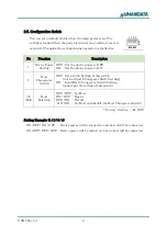
Page 9: ... on and host A will be connected ON OFF OFF OFF Device power will be turned on but no host will be connected No Function Description 1 Device Power Setting OFF Set the device power to OFF ON Set the device power to ON 2 Host Changeover Switch OFF Use pin 3 4 Setting of this switch not load host Changeover Switch setting ON Load Host Changeover Switch Setting ignore pin 3 4 setting of this switch 3...

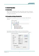
Page 10: ...tails please go to the USB 206 product web page and refer to the support documentation 3 2 Recognition and Setting of Controller Port When the port is recognized correctly the device manager displays like the following Communication setup of COM port must be set to like the following When the flow control is not active receptions of commands may be missed ...

Page 11: ...t connect to the device Status U Unlock Release Holding Device Release hold devise Connection is continued Status R Release Release Device Connection Release device connection Power status is not affected Status T Transfer Switch Device Switch the device connection to the other host Power status is not affected Status C Cold Device Power OFF Power off the device This function is valid when the hos...

Page 12: ...nected to host A 2 B Host Status Device is connected to host B 2 X Host Status Device is not connected to any host 3 L Hold Status The device is hold by the host 4 C Device Power Status The device power is off 4 V Device Power Status The device power is off because of the over current Response Example XC No host is connected and the device power is off A Host A is connected to the device and the d...

Page 13: ... X 10 Send G Connect to the device 11 Host Status LED A Light Green Response A 12 Recognize USB Memory 13 Send L Hold the connection to avoid connecting to the other host during writing data 14 Host Status LED A Light Orange Response AL 15 Write Data in USB Memory 16 Send T Switch the device connection 17 Host Status LED B Light Green Response B Recognize USB Memory 18 Send L Hold the connection t...

Page 14: ...e following documents and other supports are available at http www hdl co jp en faspc USB usb 206 z Device Driver z Outline Drawing and more 4 Warranty and Compensation Please refer to the following URL for the warranty http www fa hdl co jp en fa warranty html ...

Page 15: ...r s Manual Ver 1 0 Aug 29 2017 HuMANDATA LTD Address 1 2 10 2F Nakahozumi Ibaraki Osaka Japan ZIP 567 0034 Tel 81 72 620 2002 Japanese Fax 81 72 620 2003 Japanese English URL http www fa hdl co jp en Global http www fa hdl co jp jp Japan ...

Reviews: