020-9905 User Manual Q3 (Advanced 3 year old child) Rev G Page 27 of 82
© 2016 Humanetics Innovative Solutions
Assembly and Disassembly
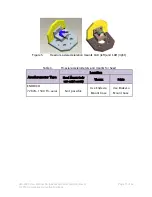
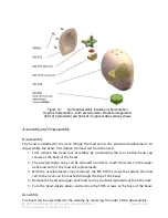
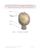
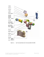
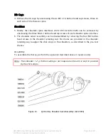
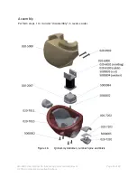
The assembly – disassembly steps are described for the head neck assembly depicted in
figure 12.
Disassembly
Head & Neck
1.
To disassemble the neck, remove the head and upper neck load cell structural
replacement as described above.
2.
After removing the head assembly and load cell structural replacement, the screws at
the base of the neck can be reached and removed.
3.
To inspect the neck-cable assembly, remove the two FHCS M3 x 8 at the top of the
neck and undo the nut at the bottom of the neck. The Neck-cable assembly can now
be pulled out from the top. The neck cable assembly should NOT be disassembled.
Note
:
Do not unscrew the screws at the bottom of the clamping plates on the neck cable
assembly. The neck cable is pre-stretched and clamped down at manufacturing,
and should not be disassembled. In case of cable damage, customers are
recommended to replace the complete neck cable assembly (020-2200). There is
no adjustable pretension in the cable. The nut (020-2204) can be tightened firmly.
Assembly
Head & Neck
Perform the steps described under disassembly in reverse order.
Instrumentation
1.
To install a load cell, first remove the load cell structural replacement. To do so,
remove the head as shown above.
2.
Remove the four M5 x 10 FHCS screws that attach the load cell to the base of the head
assembly.
3.
Remove the load cell structural replacement and install the load cell (Humanetics type
IF-217 or IF-218). The round base plate should be facing up, and the cable exits
facing downwards at the rear and the back of the neck.
4.
Fasten the load cell to the base of the head using the four M5x10 counter sunk head
cap screws.
5.
Assemble head and load cell onto the top of the neck using the four M5 x 12 SHCS
screws.

