020-9905 User Manual Q3 (Advanced 3 year old child) Rev G Page 44 of 82
© 2016 Humanetics Innovative Solutions
Assembly and Disassembly
Disassembly
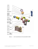
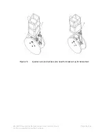
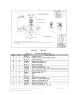
The arm should not need (dis-)assembly under normal circumstances. If the arm needs
to be removed from the dummy, then follow the procedures described in section 4.4.
1.
Remove the upper arm at the clavicle/scapula section.
2.
Remove the spring plunger (5000328) and motion stop screw (020-9901).
3.
Remove the shoulder screw connecting upper and lower parts of the arm
Assembly
1.
Perform steps 1-3 under assembly in reverse order.
2.
Check that the rubber end stops are in the correct position inside the elbow joint
before assembly of the lower arm.
3.
Align upper and lower arm at the shoulder screw hole and screw in shoulder screw.
4.
Place upper and lower arm under a 90º angle with respect to each other.
5.
Turn the motion stop screw into the arm as far as it will go. Then turn back half a turn
and check that the motion of the lower arm is without significant friction. The correct
position for motion stop screw is the inside of the arm.
6.
Screw in the spring plunger in the hole next to the shoulder screw at the outside of
the arm.
7.
Check the correct settings for the spring plungers (see chapter 5). Do not over tighten
the spring plunger.
Note:
It is not possible to change the friction setting of the elbow joint. The positioning
is done by means of the fixed “click stop” positions in the joint.
Instrumentation
No instrumentation is used in the arms.

