5
NOTE:
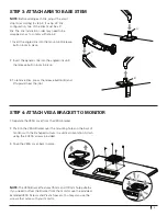
Before adding each link, adjust the smart
stop (A) according to step 2. If using a 3 link
configuration, one of the links must be a 4”
link. The link installation order may need to be
swapped so as to comply with step 2.
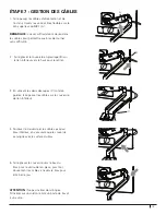
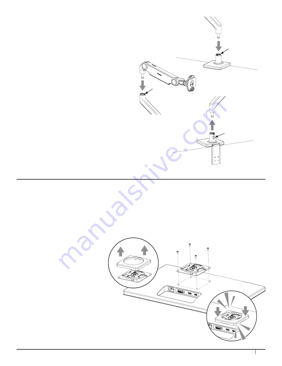
1. Insert the angled link into the mount until release
button locks in place.
2. Insert the dynamic link into the angled link until
the release button locks in place.
3. To remove links, press the release button (B) and
lift upward near the joint.
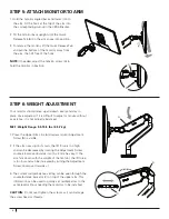
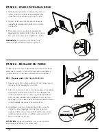
1. Separate the VESA cover from the VESA bracket.
2. Position the VESA Bracket over the mounting holes on the back of
monitor with the D-shaped cutouts in a vertical orientation. Attach
using the 4 VESA screws provided.
3. Snap the VESA cover back in place.
NOTE:
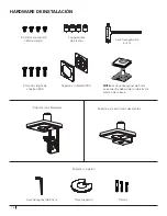
The VESA Bracket features 75mm and 100mm hole patterns.
If you need to offset the Bracket from the monitor use the provided
Extended VESA Screws and Plastic Spacers. You may also use the
screws that came with your monitor.
STEP 3: ATTACH ARM TO BASE STEM
STEP 4: ATTACH VESA BRACKET TO MONITOR
A
A
B

