background image

If there is no computer display when a PC is

connected:

• Make sure that all connectors are properly

plugged in. Particularly make sure that the

computer cable is connected to the Synergy unit

and not directly to the monitor.

• Press the

Page locator

button.

• Make sure that your computer is on and working

by connecting the PC directly to the monitor.

• Check menu configuration. Please consult the

Display Submenu section for additional

information.

• Seek help from a qualified professional if all of

the above suggestions fail.

If the image is out of focus:

• Try moving your reading material off the reading

table and then putting it back again.

• Clean the monitor screen with a glass cleaning

solution.

• Check if the Focus is set to Automatic or Fixed.

For additional information, please look for Focus

in the Main menu items section.

If the text looks gray or low in contrast:

• Press the Enhanced contrast button to set the

unit in High Contrast mode.

• Check the Brightness and Contrast. They should

be set to at least 50%. Note that the

22

Summary of Contents for SmartView Synergy

Page 1: ...Revision 4 20092709 ...

Page 2: ...for errors or omissions Nor is any liability assumed for damages resulting from the use of the information contained herein About HumanWare HumanWare http www humanware com is the global leader in assistive technologies for the print disabled HumanWare creates products for people who are blind have low vision and or have learning disabilities The innovative range of HumanWare products includes Bra...

Page 3: ...hird grounding pin and can only be plugged into a grounding type power outlet If necessary contact an electrician to replace your power outlet with a grounding type power outlet This product should be operated from the type of power indicated on the marking label If you are not sure of the type of power available consult your dealer or local power company Refer all servicing of this product to qua...

Page 4: ...Caution ...

Page 5: ...ibility The use of accessories and cables other than those specified by HumanWare may result in increased emissions or decreased imP munity of the SmartView Synergy Placement of equipment The SmartView Synergy should not be used adjacent to or stacked with other equipment FCC Warning This equipment has been tested and found to comply with the limits for a Class B digital device pursuant to part 15...

Page 6: ...ning the equipment off and on the user is encouraged to try to correct the interference by one or more of the following measures Reorient or relocate the receiving antenna Increase the separation between the equipment and receiver Connect the equipment into an outlet on a circuit different from that to which the receiver is connected Consult the dealer or an experienced radio TV technician for hel...

Page 7: ... configuration 6 1 5 2 Rear panel 7 1 5 3 Using the Reading Table 8 1 5 4 Adjusting the LCD Screen 8 2 Control panel and buttons 9 2 1 Description of control panel buttons 10 2 1 1 Power button 10 2 1 2 Enhanced contrast mode button 10 2 1 3 Color mode button 11 2 1 4 Page Locator button Advanced control panel only 11 2 1 5 Zoom knob 12 2 1 6 Line and Blinds Advanced control panel only 12 2 1 7 Br...

Page 8: ...GA IN VGA OUT and TV Output 18 4 1 VGA IN 19 4 2 VGA OUT Standard configuration with Advanced Control panel only 20 4 3 TV output 20 5 Maintenance and Troubleshooting 21 5 1 Maintenance 21 5 2 Troubleshooting 21 6 Returning for Service 25 7 Safety Precautions 26 8 Technical Specifications 27 9 Manufacturer Warranty 30 ...

Page 9: ...n eye conditions 1 2 Unpacking the system The package contains the following items Synergy Base unit LCD screen optional Control panel User Guide Getting Started Guide Tutorial DVD 1 3 Configurations The SmartView Synergy is available in two configu rations The Base configuration does not have an integrated LCD screen Users will have to connect their own LCD screen It also comes with a Standard re...

Page 10: ...tional Note Remote control panels are attached to the base of the unit by a cable Fixed control panels are attached to the integrated LCD screen and are there fore only available with the standard configuration All features of the Standard control panel are also found on the Advanced control panel The Advanced Control panel however has two additional buttons 1 4 Assembly 1 Remove Base unit from Bo...

Page 11: ...rom top of base unit Position the tabs on bottom of the arm over the two slots on the metal structure Lower the LCD and arm so the tabs fit into the lots and slide the LCD arm to the rear The LCD ARM unit should hold itself 3 ...

Page 12: ...des of the arm 5 Connect the cable to the matching connector through the hole in the top Use a screwdriver to tighten the connector 6 Place the plastic piece over the bottom the arm 4 Step 5 Place the plastic piece over the bottom the arm ...

Page 13: ...c piece at the front of the base of the arm Warning Do not lift the unit by the arm Only lift by holding the bottom of the base 7 Place the small plastic piece at the front of the base of the arm 8 Connect the power supply and cable ...

Page 14: ...al description of SmartView Synergy 1 5 1 SmartView Synergy Standard configuration 1P LCD screen 2P Front Control panel 3P Camera and Page Locator Light 4P Table Lock 5P Reading Table 6P Rear panel 6 1 2 3 4 5 6 ...

Page 15: ...f a LCD Screen or Fixed Front Control panel Users must connect their own LCD screen and attach a Remote Control panel 1 5 2 Rear panel 1P Power connector 2P USB maintenance port 3P Remote control panel connector 4P TV OUT connector 5P VGA OUT connector 6P VGA IN connector 7 1 2 3 4 5 6 ...

Page 16: ...e of the Reading table To increase the resistance of the Reading Table move the slider to the right The more you push the slider to the right the more difP ficult it will be to move the Reading Table This will provide you with more control and will decrease the chances of accidentally moving away from what you were viewing When the slider is completely to the right the Reading table will be in loc...

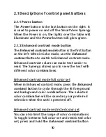
Page 17: ...ontrol panel and buttons From left to right the Control panel is comprised of the following buttons and knobs 1 Enhanced contrast button 2 Color button 3 Page Locator button Advanced Control panel only 4 Zoom knob 5 Line and blinds button Advanced Control panel only 6 Brightness knob 7 Power button 9 1 2 4 6 7 Standard Panel 1 2 3 4 5 6 7 Advanced Panel ...

Page 18: ...ch to Enhanced contrast mode Enhanced contrast colors can make text easier to read The Synergy allows you to view the text with different color combinations Enhanced contrast mode full color set When in Enhanced contrast mode press the Enhanced contrast button to cycle through the 16 foreground and background color combinations The selected color combination will be saved as your preferred selecti...

Page 19: ...ilable choices to these 2 combinations Note The Enhanced contrast button is also used to Exit the menu and the Line and Blinds feature 2 1 3 Color mode button When in Enhanced contrast mode use the Color button to switch to Color mode In this mode images will be displayed in full color Note When in viewing mode pressing and holding the Color button for 2 seconds will activate the Main menu When in...

Page 20: ...o increase magnification or turn counterclockwise to decrease magnification There are 24 different magnification levels 2 1 6 Line and Blinds Advanced control panel only Line and Blinds is a feature that can help you control what appears on screen The line can help you separate what appears on screen while the blinds can be useful to block unwanted sections of the text Short presses of the Line an...

Page 21: ...htness knob clockwise or counterclockwise to increase or decrease the Brightness level Separate brightness levels will be saved for Enhanced Contrast or Color modes Notes When in the Menu the Brightness knob is used to cycle through menu options The Bright ness knob is also used to adjust Brightness Color or Contrast through the menu When Using the Line and Blinds option Advanced control panel onl...

Page 22: ...an option The Enhanced contrast button is used to move up from the Display submenu to the Main menu It is also used to exit the Main menu 3 2 Using Sliders Sliders are used when accessing the Brightness Contrast and Color menu items When a slider is displayed use the Brightness knob to make adjust ments A clockwise rotation of the Brightness knob will increase the value of the parameter while a co...

Page 23: ...els Contrast can only be adjusted in Color mode Any attempt to adjust contrast in Enhanced contrast mode will result in an error beep Color Color mode only Selecting this menu item will display a Color slider bar that will allow you to adjust color levels Colors can only be adjusted in Color mode Any attempt to adjust color in text mode will result in an error beep Color Preset Color mode only Thi...

Page 24: ...o turn off and on the lights illuminating the table Beep This menu item allows you to disable nonPessential system beeps Error beeps will remain activated Display This menu item is used to access the Display subP menu The Display submenu includes the following items Language Region System Information Zoom Display Splash Screen Screen Size Video Switch and PCPScreen Video Link These will be describ...

Page 25: ...ecting this option will display the splash screen normally seen when starting the system Zoom Display Select this option to enable or disable the zoom level display when adjusting magnification Splash Screen This menu item is used to enable or disable the splash screen when the system is started Screen Size Use this option to set the size of the screen used When using zoom this will allow you to h...

Page 26: ...y Video Switch settings will be saved when the system is shutdown Note that on the base configuration where an LCD screen cannot be attached the Video Switch paraP meter cannot be changed to Output Any attempt to do so will result in an error beep PC Screen video link Turn this option on if you wish to send the VGA IN signal to the screen when unit is turned off This is useful if your computer is ...

Page 27: ... Make sure the Video switch option is set to INPUT For additional information please consult the Display Submenu section Video Switch item The PCPScreen video link option must be set to ON For additional information please consult the Display Submenu section Video Pass Through item With both the computer and SmartView unit powered on press and hold the Page Locator Button to alternate the image so...

Page 28: ...e sure the Video switch option is set to OUTPUT For additional information please consult the Display Submenu section Video Switch item Make sure to power on the screen Press and hold the Page Locator button to switch screens 4 3 TV output The SmartView can output images to a TV screen To do so connect the TV to the SmartView s TV OUT port using a composite video cable When a TV is connected to th...

Page 29: ...he other end of the Universal power supply is connected to the SmartView Check that the power is switched on at the wall socket Check that the green power light is glowing Check that all cables are properly plugged in Check that the monitor is switched on This only applies to external monitors The LCD screen Standard configuration is automatically powered when the unit is turned on Check that the ...

Page 30: ...tion for additional information Seek help from a qualified professional if all of the above suggestions fail If the image is out of focus Try moving your reading material off the reading table and then putting it back again Clean the monitor screen with a glass cleaning solution Check if the Focus is set to Automatic or Fixed For additional information please look for Focus in the Main menu items ...

Page 31: ...heck that the lights over the reading table are working If the contrast is low Check the Contrast setting in the menu The contrast can only be adjusted in Color mode If the brightness is low Check the Brightness Use the Brightness knob to make adjustments Remember that there are different settings for Color and Enhanced contrast modes Check that both lights over the reading table are working If th...

Page 32: ...ress the Enhanced contrast button to make sure that the SmartView Synergy is in Enhanced contrast mode Press and hold the Enhanced contrast button for five seconds until you hear a beep If you are stuck in the menu Press the Enhanced contrast button Press the Power button to switch off the machine then press the Power button again to switch on and restart If the Start Up screen stays on Press the ...

Page 33: ...Reading Table is locked if the Slider is at the rightmost position To unlock and reduce friction move the slider to the left Make sure there are no obstructions around your work area preventing you from moving the table The table s track must also be unobstructed Other problems Turn the SmartView Synergy on and off 6 Returning for Service If you have a problem with your SmartView Synergy please co...

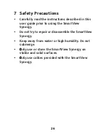
Page 34: ...guide prior to using the SmartView Synergy Do not try to repair or disassemble the SmartView Synergy Keep away from water or high humidity Do not submerge Only use or store the SmartView Synergy on stable and solid surfaces Only use cables provided with the SmartView Synergy 26 ...

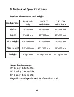
Page 35: ...ay 3 1x to 69x Magnification depends on size of monitor used 27 Configuration Base unit only 19 LCD with Base 22 LCD with Base Width 14 355mm 14 355mm 20 508 mm Depth 19 482 mm 21 533 mm 21 533 mm Min Height 11 5 292 mm 21 533 mm 21 533 mm Max Height 11 5 292 mm 25 635 mm 25 635 mm Weight 10kg 22lbs 15 6 kg 34 5 lbs 15 7 kg 34 6lbs ...

Page 36: ...y 47P63 Hz Input current 0 9A Power usage 77W PC Compatibility The SmartView connects to desktop laptop or noP tebook computers with equipped with VGA display It can display PC and camera images alternately Video modes 19 LCD screen 720x400 70Hz 800x600 60Hz 75Hz 1024x768 60Hz 75Hz 1280x1024 60Hz 75Hz 28 ...

Page 37: ...1 1 Type of Protection Class 1 Degree of Protection Type B Enclosure Degree of Protection IP20 Mode of Operation Continuous Environmental Operating Temperature 10 to 40º C Transport Storage Temperature P20 to 60º C Operating Humidity 20 to 80 RH Transport Storage Humidity 10 to 95 RH Operating Altitude P200 to 2000 m Transport Storage Altitude P200 to 12 000 m 29 ...

Page 38: ... please contact your local distributor or the manufacturer Note Warranty terms may periodically change please consult our website for the latest information Conditions and Limitations No replacement or repair covered by the warranty will be carried out unless the unit is accompanied by a copy of the original bill of purchase Please retain your original If the unit has to be returned please use the...

Page 39: ...Please contact HumanWare or check on our website for versions of this manual in other languages 31 ...

Page 40: ...Warning Avoid exposure to moisture rain sand and extreme temperatures REV00 ...

Reviews: