Load securing
3
50
Operation
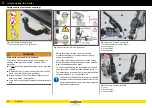
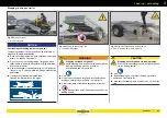
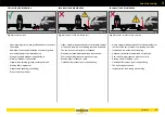
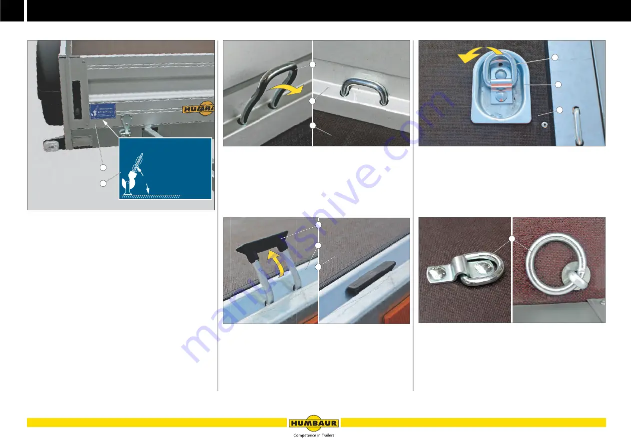
Tie-down points in / on the cargo bed
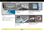
Fig. 55
Example: Tie-down force information
1
Sticker
2
Front drop side
Check that the number of tie-down points and the max.
tie-down forces are sufficient for the goods to be tied
down.
If applicable, fit more lashing points.
Replace any damaged / worn tie-down points.
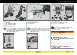
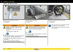
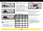
Tie-down points
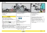
Fig. 56
Tie-down brackets which can be recessed
Tie-down force = max. 400 daN (kg)
1
Tie-down bracket
2
Drop wall profile
3
Cargo bed (floor plate)
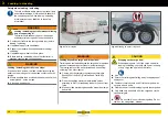
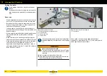
Fig. 57
Tie-down brackets which can be recessed
Tie-down force = max. 800 daN (kg)
1
Tie-down bracket
2
V lashing rail
3
Cargo bed (floor plate)
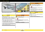
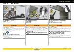
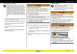
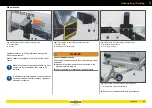
Fig. 58
Recessed tie-down points (optional)
Version 1: Tie-down force = max. 200 daN (kg)
Version 2: Tie-down force = max. 400 daN (kg)
1
Tie-ring
2
Trough recess
3
Cargo bed (floor plate)
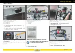
Fig. 59
On-surface tie-down points (optional)
Tie-down force = max. 200 daN (kg)
1
Tie-ring,
screwed onto the cargo bed
B - 072
DIN Zurrpunkte
400
daN
(kg)
min. 30 °
620.00031_B
2
1
B - 073
1
2
3
B - 074
1
2
3
B - 075
1
2
3
B - 076
1
Summary of Contents for 1000 Series
Page 1: ...GENERAL CAR Program PART 1 OPERATING MANUAL humbaur com 1000 8400 SERIES EN ...
Page 9: ...1 7 Safety ...
Page 21: ...2 19 General information ...
Page 31: ...3 29 Operation ...
Page 67: ...3 65 Operation Trailer safety ...
Page 75: ...4 73 Chassis ...
Page 103: ...5 101 Body ...
Page 134: ...Cover net 5 132 Body ...
Page 135: ...6 133 Electrical system ...
Page 145: ...7 143 Testing care and maintenance ...
Page 185: ...8 183 Troubleshooting guide ...
Page 194: ...Hydraulics 8 192 Troubleshooting guide ...
Page 195: ...9 193 Proof of inspection ...

