4
Support devices
74
Chassis
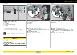
Jockey wheel
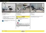
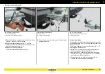
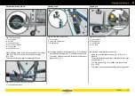
Fig. 1
Automatic jockey wheel (firmly attached)
1
Jockey wheel
2
Cylinder
Jockey wheel
–
Supporting the drawbar when parking / manoeuvring.
–
At a support load > 50 kg, a jockey wheel is installed.
–
Various jockey wheels: Weight load
Standard to raise, automatic jockey wheel, jockey wheel
with pivot bearing.
Automatic jockey wheel
–
Wheel which can be automatically folded in and out
(Fig. 1 /1).
–
Raising and lowering the cylinder (Fig. 1 /2) is not
required.
Swivel jockey wheel
–
Attached to the side of the drawbar.
–
Can be pivoted horizontally, e.g. for load-through
function.
Retrospective installation only in designated
attachment points.
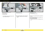
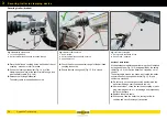
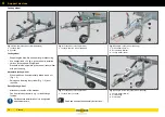
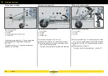
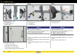
Fig. 2
Jockey wheel manual (to raise)
1
Jockey wheel (on side of drawbar)
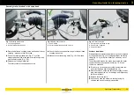
Fig. 3
Jockey wheel manual (to raise)
1
Jockey wheel (in centre)
Read and observe the assembly instructions.
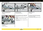
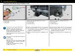
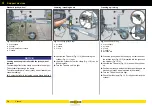
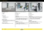
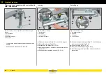
Fig. 4
Example: Jockey wheel (pivoting)
1
Crank handle (fold in)
2
Screw clamp retainer
3
Jockey wheel (fixed)
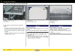
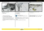
Fig. 5
Example: Automatic jockey wheel (pivoting)
1
Jockey wheel (fold-in)
2
Pivot bearing
3
Pin locking
F - 084
1
2
F - 028
1
F - 086
1
F - 033
1
2
3
F - 085
1
2
3
Summary of Contents for 1000 Series
Page 1: ...GENERAL CAR Program PART 1 OPERATING MANUAL humbaur com 1000 8400 SERIES EN ...
Page 9: ...1 7 Safety ...
Page 21: ...2 19 General information ...
Page 31: ...3 29 Operation ...
Page 67: ...3 65 Operation Trailer safety ...
Page 75: ...4 73 Chassis ...
Page 103: ...5 101 Body ...
Page 134: ...Cover net 5 132 Body ...
Page 135: ...6 133 Electrical system ...
Page 145: ...7 143 Testing care and maintenance ...
Page 185: ...8 183 Troubleshooting guide ...
Page 194: ...Hydraulics 8 192 Troubleshooting guide ...
Page 195: ...9 193 Proof of inspection ...

