18/56
V 03/2018
Original
Operati ng Instructi on Manual
6.4.2 Coupling / uncoupling
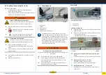
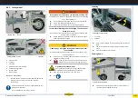
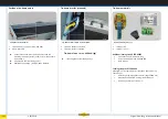
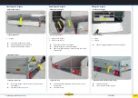
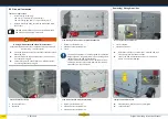
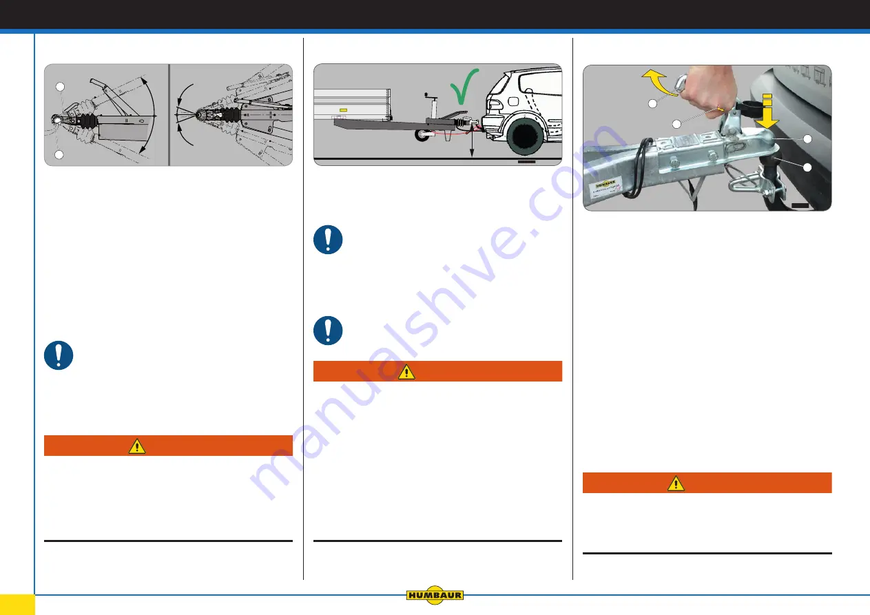
Maximum swivel range
1.
Trailer coupling (ball head) on towing vehicle
2.
Coupling head (trailer)
►
Before connecti ng up your trailer for the fi rst ti me, make
sure that the car trailer coupling is aligned with the cou
pling head on the trailer:
•
Height of both couplings
•
Design of the car coupling
•
Electrical connecti on (plug: 7 or 13-pin)
Only to be used with ball head coupling according to
Directi ve 94/20/EC or ECE R55 with a 50 mm Ø ball
head.
Limited swivel range!
Short / incorrect car couplings can limit the necessary swivel
range - trailer could come uncoupled.
►
Use a trailer coupling with a free-standing ball head.
►
Before setti ng off , check that your car coupling allows the
necessary swivel movement horizontally and verti cally.
20°
20°
25°
25°
1
2
H - 019
WARNING
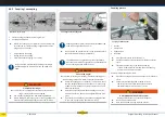
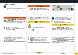
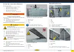
The height of the coupling head
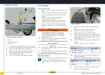
Coupling heads for trailers are built to DIN 74058 or ISO
1103 with a height of 430 ± 35 mm.
►
Do not drive with a trailer which is at an extreme angle to
the car (or ti lted forwards or backwards).
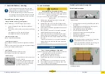
The ball head must be greased to prevent premature
wear and the formati on of grooves on the ball head and
in the coupling housing (spherical cup).
Trailer at an angle!
The required swivel range is limited / increased coupling wear /
road handling is impaired - trailer could come uncoupled.
►
Before connecti ng up your trailer for the fi rst ti me, check
that the height of the ball head on the car is in the range
of 395 - 465 mm between the road surface and the mid
dle of the ball head.
►
Adjust the height of the ball head coupling on the car or
pad out the overrun device if the height diff erence is too
great.
►
If necessary, have a diff erent ball head coupling att ached
to your towing vehicle in a specialist workshop.
H - 020
430
±
35
WARNING
Coupling process
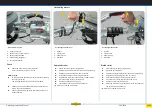
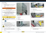
Coupling unbraked trailer
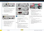
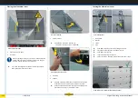
1.
Handle
2.
Safety catch
3.
Spherical cup
4.
Ball head
►
Press the safety catch (2) all the way in.
►
Pull the handle up (1) completely and release the safety
catch.
►
Place the spherical cup (3) on the ball head (4).
If there is suffi cient drawbar load, then the coupling
head will click into place by itself.
If there is insuffi cient drawbar load:
►
Press the coupling head down manually unti l it clicks into
place.
►
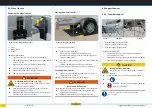
Check that the coupling head is seated correctly.
- The safety catch must lock the handle into place.
- The wear indicator is in the green / + area.
WARNING
Deformed handle and safety catch!
Damage / deformati on can cause malfuncti ons!
►
Do not stand on the handle.
►
Have the ball head coupling replaced if faulty.
3
4
1
2


