background image

The following GPS functionality is currently supported by the 900 Series™
Chartplotter when it is connected to the included GPS receiver:

• View current position

• View current track (breadcrumb trail)

• View precision speed and heading from your GPS receiver

• Save tracks, waypoints and routes

• Travel a route and navigate from one waypoint to the next.

Your 900 Series™ supports Navionics® Gold, HotMaps™ and HotMaps™
Premium on MMC or SD card media. 

NOTE:

Your 900 Series™ does not support Navionics® Classic Charts, only

Navionics® Gold,  HotMaps™, and HotMaps™ Premium. 

Your unit also comes with a built-in UniMap™ with a more detailed map of
North America (Domestic models) or a more detailed map of Europe and
Southeast Asia, including Australia and New Zealand (International models).

Your 900 Series™ uses the GPS Receiver to determine the position of the
boat automatically, and uses the zoom level settings on a particular view to
select the best chart to display. See 

Viewing Cartography

for more

information.

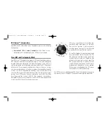
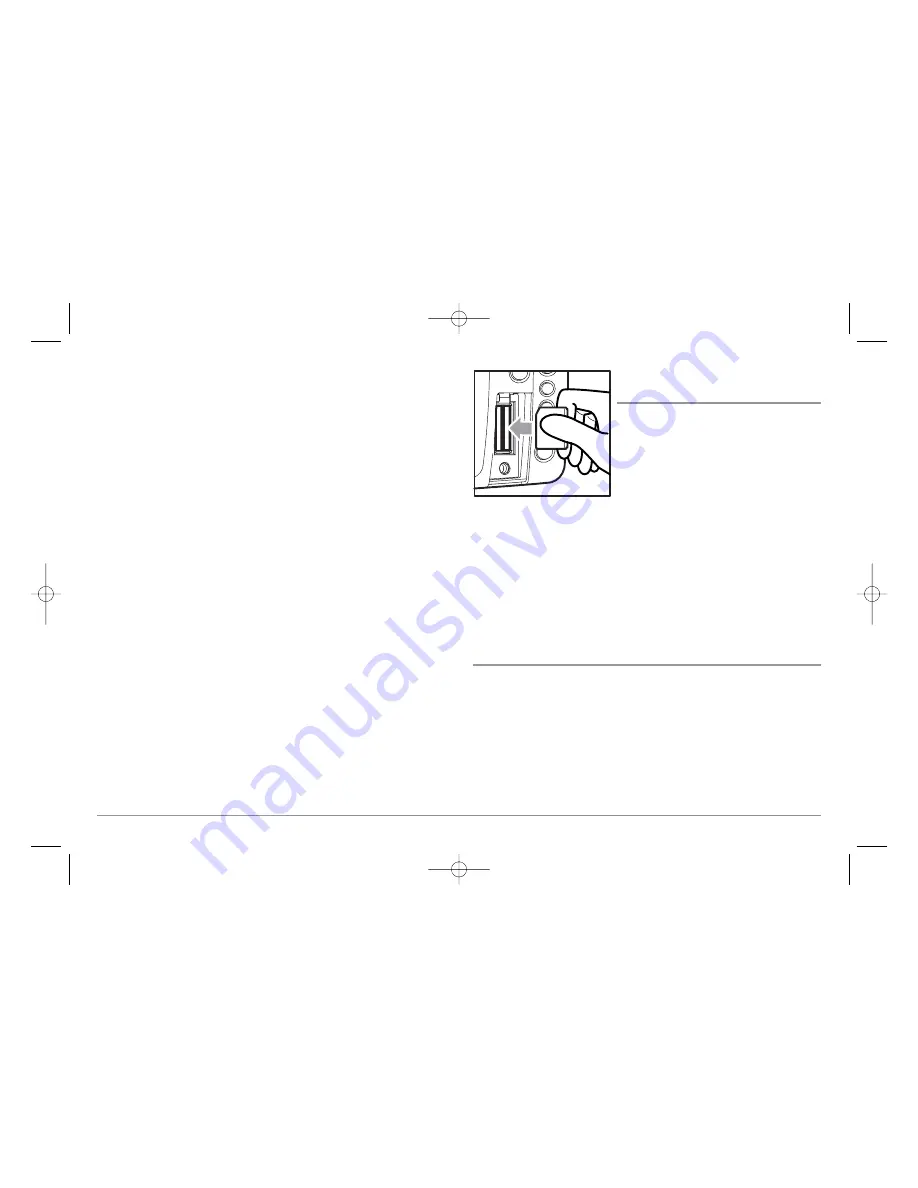
Multi-Media Card 
(MMC)/SD Slot

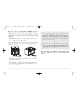
Your 900 Series™ Chartplotter also has a
multi-media card (MMC)/SD slot that is used
to insert optional-purchase cards containing
additional detailed maps. If you insert an
MMC/SD that contains a more detailed
chart for a particular location, your 900
Series™ Chartplotter will retrieve that chart
and display it automatically. Use the

illustration to locate the position of the MMC/SD slot cover, remove the
MMC/SD slot cover, then insert the MMC/SD into the slot. The label on the
MMC/SD should face toward the left side of the unit. Press down on the
card until it clicks into place and replace the slot cover. Then, replace and
tighten snugly - do NOT overtighten, as this will not improve water
resistance, and may damage the cover.

Software Updates

Use the MMC/SD slot to update the software version of your control head.
To update the software in your control head, plug in the appropriate
MMC/SD card that contains a software update file; the unit will recognize it,
will tell you what software version your control head is currently running,
and will ask you if you want to update the software in the unit to match that
on the MMC/SD card. You can obtain software updates from the

www.humminbird.com

website.

Inserting an MMC/SD 

into the Card Slot

2

531569-1_B - 955c ManE.qxp  3/4/2007  5:03 PM  Page 2

Summary of Contents for 955C

Page 1: ...531569 1_B 955c ManE qxp 3 4 2007 5 03 PM Page 1...

Page 2: ...ckly to allow time for you to react Always operate the boat at very slow speeds if you suspect shallow water or submerged objects WARNING Disassembly and repair of this electronic unit should only be...

Page 3: ...Routing the Cable and Check GPS Receiver Operation 12 Testing the System Installation 13 Getting Started Using Your 900 Series 14 Powering Up the Control Head 14 What s on the Display 15 Key Functions...

Page 4: ...plit Position 45 Waypoint Name only with an active cursor on a waypoint 46 Cursor to Waypoint Chart or Combo view only 46 Save Current Track 47 Clear Current Track 47 Save Current Route only when navi...

Page 5: ...ndings 64 Navaids on Bird s Eye View 65 Shaded Depth 65 Set Simulation Position Advanced 65 Set Map Offset Advanced 66 Clear Map Offset Advanced 66 Alarms Menu Tab 67 Low Battery Alarm 67 Aux Temp Ala...

Page 6: ...900 Series Chartplotter Accessories 84 Specifications 85 Glossary 86 Contact Humminbird 90 NOTE Entries in this Table of Contents which list International only are only available on products sold out...

Page 7: ...tion from WAAS the Wide Area Augmentation System EGNOS the European Geostationary Navigation Overlay Service and MSAS the MTSAT Satellite Augmentation System satellites if they are available in your a...

Page 8: ...a multi media card MMC SD slot that is used to insert optional purchase cards containing additional detailed maps If you insert an MMC SD that contains a more detailed chart for a particular location...

Page 9: ...al details NOTE Accessories to enable WeatherSense and the SmartCast Wireless Sonar Link require separate purchases You can visit our website at www humminbird com or contact our Customer Resource Cen...

Page 10: ...ese accessories online or contact our Customer Resource Center at 1 800 633 1468 Control Head Installation You have two choices for mounting your 900 Series control head Gimbal mounting where you use...

Page 11: ...st to start with a smaller bit and use progressively larger drill bits to reduce the chance of chipping or flaking the outer coating Fill all holes with marine grade silicone sealant NOTE You must hav...

Page 12: ...mounting screws Remove the hole cover drill the two mounting holes using a 9 64 3 5 mm bit fill them with marine grade silicone then replace the hole cover and insert the 8 Phillips countersink wood...

Page 13: ...connectors into the wrong slots If you don t have a cable for every hole in the insert install the blank plugs to protect the control head from the weather 1 2 Cables Routed Behind Mounting Bracket 3...

Page 14: ...reful not to force the connectors into the wrong sockets Once the cable collector and all cables are plugged into the back of the control head lock the assembly into place by threading the knurled scr...

Page 15: ...must have adequate protection through the proper selection and installation of a 3 Amp fuse NOTE In order to minimize the potential for interference with other marine electronics a separate power sou...

Page 16: ...st the cable routing to your control head before any drilling or cutting of your boat surfaces If you have purchased hardware to stem mount your GPS receiver follow the instructions included with that...

Page 17: ...unit configuration 2 Mark the mounting location and drill a 3 4 19 mm hole for the cable and cable plug Route the cable 3 Cover the cable hole with the receiver Make sure the receiver is flush on the...

Page 18: ...hes Use the cable notch closest to the intended cable route 4 With the cable routed position the GPS receiver in the planned mounting location and mark the mounting holes with a pencil or punch 5 Move...

Page 19: ...too long the system will default to whichever menu mode happens to be highlighted and you will have to start again 2 Self Test displays results from the internal diagnostic self test including unit s...

Page 20: ...on Warning screen is shown Press the MENU key during the time that the Title screen is displayed to view the Start Up Menu in order to choose Simulator mode Press the EXIT key during the Navigation Wa...

Page 21: ...t that projects your current course and shows wheretheboatwillgoifyoucontinueonyour present course Route Two or more linked waypoints that show intended navigation and the shortest path from one waypo...

Page 22: ...wer up To adjust the backlight or to adjust the display background color press the POWER LIGHT key to access the Light and Background menu Use the 4 WAY Cursor key to select Light or Background and th...

Page 23: ...to select the menu item and the LEFT or RIGHT key to alter a menu setting 4 WAY Cursor Control Key The 4 WAY Cursor Control Key has multiple functions depending on the situation Active Cursor In any B...

Page 24: ...w to mark the position of a waypoint either at the current boat location or if the Cursor is active at the current Cursor location The MARK key only functions if you have the GPS receiver connected or...

Page 25: ...Keys Press the or ZOOM keys while in any of the Navigation Views to change the scale of the view to appear closer or farther away Views The views available on your 900 Series are Bird s Eye Bird s Eye...

Page 26: ...e to the screen Views and Readouts All views have an Information Bar on the left side of the screen consisting of readouts that are stacked vertically and that change from view to view You can customi...

Page 27: ...other view See Navigation X Press menu Select Readouts for more information NOTE If there is only one waypoint in a route the Next Waypoint and the End Waypoint info boxes will display the same inform...

Page 28: ...pressing the DOWN arrow key moves the eye point backward Pressing the EXIT key moves the eye point back to its original position behind and above the boat Bird s Eye Big Digits View COG Course Over Gr...

Page 29: ...e way for navigation mode and another way for non navigation mode When you change the readouts display on one of these views you also are changing them on all the other views that share the same confi...

Page 30: ...ectable readouts that can all be set one way for navigation mode and another way for non navigation mode When you change the readouts display on one of these views you also are changing them on all th...

Page 31: ...me set of 5 selectable readouts that can all be set one way for navigation mode and another way for non navigation mode When you change the readouts display on one of these views you also are changing...

Page 32: ...w Chart No Readouts View Chart Chart Combo View and Chart Bird s Eye Combo View all share the same set of 5 selectable readouts that can all be set one way for navigation mode and another way for non...

Page 33: ...titude and Longitude Position of Boat Bearing of Cursor 4 11 NEXT Next Waypoint in the Route Cursor Icon 5 12 TTG Time to Go to Waypoint Boat Icon 6 13 DTG Distance to Go to Waypoint Route 7 14 1 2 4...

Page 34: ...ling measured in degrees from North ETA Estimated time of arrival 1 9 SOG Speed Over Ground the measurement of the boat s progress across a given distance and is the speed measurement provided by GPS...

Page 35: ...lect Readouts for more information NOTE If there is only one waypoint in a route the Next Waypoint and the End Waypoint info boxes will display the same information both for that next waypoint Chart I...

Page 36: ...WAY Cursor keys to see the whole list of thumbnails in this view The selected thumbnail will be highlighted with arrows NOTE The speed of the screen capture depends on the type of card you use in gene...

Page 37: ...creen snapshots is a four step process 1 Enabling Screen Snapshot from the Accessories Menu 2 Making a Screen Snapshot using the MARK key 3 Viewing a Screen Snapshot using the Screen Snapshot View 4 D...

Page 38: ...is linked to the boat by a yellow line even if the boat is off the screen At the same time a cursor dialog box is displayed at the top of the screen with the distance and bearing from the boat to the...

Page 39: ...e tide station position The cursor information boxes will indicate the distance and bearing to the tide station from your present position Press the EXIT key again to return to the Chart View Nearest...

Page 40: ...crumb trail of trackpoints The Current Track shows the position history since the unit was powered up maximum of 20 000 trackpoints displayed You can clear the Current Track or save it at any time You...

Page 41: ...e RIGHT Cursor key Use the Cursor keys to program a waypoint name latitude longitude and icon before selecting Save Edit a waypoint From the Waypoints submenu select Edit and press the RIGHT Cursor ke...

Page 42: ...key Canceling navigation removes the route and any waypoints created using the GOTO key but does not remove any saved routes from memory You will be prompted to save the current route when you cancel...

Page 43: ...key twice to display the Main Menu System then use the RIGHT Cursor key to select the Navigation tab Select Routes and press the RIGHT Cursor key to display the Routes submenu Create a route From the...

Page 44: ...System then use the RIGHT Cursor key to select the Navigation tab Select Tracks and press the RIGHT Cursor key to display the Tracks submenu Edit a saved track From the Tracks submenu select Edit and...

Page 45: ...that shows the lat lon position of the MOB waypoint and the elapsed time since MOB was activated is added to the Chart View It is not possible to re activate MOB or modify the current route without f...

Page 46: ...specific menu item quickly Main tab headings are Alarms Navigation Chart Setup Views and Accessories Press the MENU key twice for the Main Menu then use the 4 WAY Cursor LEFT or RIGHT key to select a...

Page 47: ...ate when you change any menu settings that affect the Sonar View the view will update immediately i e you don t have to exit the menu to apply the change to the screen Start Up Options Menu Press the...

Page 48: ...mal mode Simulator Use the Simulator to learn how to use your 900 Series before taking your boat on the water The Simulator is a very powerful tool that simulates on the water operation providing a ra...

Page 49: ...lf Test Self Test displays results from the internal diagnostic self test including unit serial number Printed Circuit Board PCB serial number software revision total hours of operation and the input...

Page 50: ...et being used This view also reports the current position local time and date and other numeric information The current GPS Fix Type is reported as No Fix 2D Fix 3D Fix or Enhanced An Enhanced fix has...

Page 51: ...on the Navigation X Press Menu 2 Use the RIGHT 4 WAY Cursor Control key to change which side is active Left Right Default Right Split Position Split Position allows you to adjust what percentage of t...

Page 52: ...o Views Delete allows you to delete a waypoint from the list of saved waypoints Target allows you to apply a target to a waypoint selected from the list of waypoints Grid allows you to apply a trollin...

Page 53: ...rent track press the LEFT Cursor key Save Current Route Only when navigating Save Current Route allows you to save the current route being displayed This menu choice will only appear when you are curr...

Page 54: ...on 1 Highlight Cancel MOB Navigation on the Navigation X Press menu 2 Use the RIGHT 4 WAY Cursor Control key to initiate canceling MOB navigation 3 The Confirm dialog box will appear To cancel MOB nav...

Page 55: ...w the Waypoints submenu The Waypoint Submenu contains the following menu choices Edit allows you to edit the Name Position Latitude and Longitude and select the Icon that will be used to represent the...

Page 56: ...for more information Also you can set these 5 readouts with navigation mode settings so that when you are navigating these views contain navigation data instead of the regular settings See Navigation...

Page 57: ...e The TRK is measured in degrees See above for an explanation of Course Made Good TTG Time To Go Time To Go is the estimated time required to reach the destination waypoint TTG is calculated using the...

Page 58: ...d the last waypoint on the route Water Speed The current speed of the water as it flows past the boat WPTnext ETA DTG Waypoint Next Estimated Time of Arrival Distance to Go Waypoint Next is the next w...

Page 59: ...ixed position data windows arranged at the left edge of the screen on various views or whether a particular window will be turned off displaying nothing in that area Data windows can display readouts...

Page 60: ...ck XTE measures how far the boat is off course and also triggers the Off Course Alarm 5 Selectable Data Windows Used by Standard Chart Views Navigation Mode cont Bearing Bearing is the direction to a...

Page 61: ...keys to select a particular readout position then use the RIGHT or LEFT Cursor keys to change what will be displayed at that position NOTE The selections for each readout will vary depending on which...

Page 62: ...o select the image you want to delete 2 Highlight Delete Image on the Screen Snapshot X Press menu 3 Press the RIGHT 4 Way Cursor key to initiate this procedure 4 A Confirm Dialog box will ask if you...

Page 63: ...Track allows you to save the current track Clear Current Track allows you to clear the current track Appearance allows you to change the style and color of the current track Breadcrumb Trail Dashed L...

Page 64: ...w the Waypoints submenu To view the Waypoints Submenu 1 Highlight Waypoints on the Navigation main menu 2 Use the RIGHT 4 WAY Cursor Control keys to view the Waypoints submenu The Waypoints Submenu co...

Page 65: ...s on the Navigation main menu 2 Use the RIGHT 4 WAY Cursor Control keys to view the Routes submenu The Routes Submenu contains the following menu choices Create allows you to create a new empty route...

Page 66: ...Waypoints for information on how to set a Grid To change the Trolling Grid Rotation setting 1 Highlight Trolling Grid Rotation on the Navigation main menu 2 Use the LEFT or RIGHT 4 WAY Cursor Control...

Page 67: ...increase the track resolution Track Color Range Track Color Range allows you to set the depth range that will be displayed as black the deepest depth when Color By Depth is selected as the style for...

Page 68: ...ight Export All Nav Data on the Navigation main menu 2 Use the RIGHT 4 WAY Cursor Control key to export all navigation data Delete All Nav Data Advanced Delete All Nav Data allows you to delete all sa...

Page 69: ...avigation routes in addition to the Basic information Underwater shows depth contours fishing areas underwater wrecks tides and currents in addition to the Basic and Navigation information All shows r...

Page 70: ...ight Lat Lon Grid on the Chart main menu 2 Use the LEFT or RIGHT 4 WAY Cursor Control keys to change the Lat Lon Grid setting Hidden Visible Default Hidden Spot Soundings Spot Soundings allows you to...

Page 71: ...ys to change the Shaded Depth setting Off 1 to 60 Feet or 1 to 20 Meters International Units only Default 15 ft 5 m Set Simulation Position Advanced Set Simulation Position allows you to set the posit...

Page 72: ...ffset on the Chart main menu 3 Use the RIGHT 4 WAY Cursor Control key to set the Map Offset A confirmation dialog box will appear to allow you to change your mind or to confirm your choice If the curs...

Page 73: ...r the battery that is connected to the 900 Series The Low Battery Alarm should be set to warn you when the battery voltage drops below the safety margin that you have determined For instance if you ar...

Page 74: ...main menu 2 Use the LEFT or RIGHT 4 Way Cursor Control keys to change the Aux Temp Alarm setting Off 33 120 Fahrenheit 0 50 Celsius Default Off Temp Alarm Temp Alarm sounds when the water temperature...

Page 75: ...300 ft 100 m Arrival Alarm Arrival Alarm sounds when the boat has either exceeded the distance to the destination waypoint or has entered the Arrival Alarm Circle based on the menu setting when naviga...

Page 76: ...he LEFT or RIGHT 4 WAY Cursor Control keys to change the Drift Alarm setting Off 25 to 3000 feet 10 to 1000 meters International models only Default Off Alarm Tone Alarm Tone selects the pitch of the...

Page 77: ...ing 1 Highlight Units Depth on the Setup menu 2 Use the LEFT or RIGHT 4 WAY Cursor Control keys to change the Units Depth setting Meters International models only Feet Fathoms Default is Meters for In...

Page 78: ...HT 4 WAY Cursor Control keys to change the Units Speed setting kph International models only mph kts Default kph for International models and mph for Domestic models User Mode User Mode sets the menu...

Page 79: ...faults press the LEFT Cursor key Aux Temp Offset Advanced Aux Temp Offset will adjust the aux temperature readout the temperature on the optional purchase temperature probe or Temp Speed accessory by...

Page 80: ...ntrol keys to change the Local Time Zone Default EST UTC 5 Eastern Standard Time Daylight Saving Time Advanced Daylight Saving Time adjusts the time display to account for local Daylight Saving Time S...

Page 81: ...at for the date display when Time Date is selected as a Digital Readout see Navigation X Press Select Readouts To change the Date Format 1 Make sure you are in Advanced User Mode then highlight Date F...

Page 82: ...t Sentence B BWR Bearing and Distance to Waypoint RMB Recommended Minimum Navigation Info To turn NMEA Output on or off 1 Make sure you are in Advanced User Mode then highlight NMEA Output on the Setu...

Page 83: ...le The following views are available To Change the View Status of Any View 1 Highlight the View main menu tab 2 Use the UP or DOWN 4 WAY Cursor Control keys to select a View 3 Use the LEFT or RIGHT 4...

Page 84: ...d and saved automatically Once you have created a screen capture a screen capture thumbnail is added to the Screen Snapshot View and is available to view at a later date See the full sized image by hi...

Page 85: ...shots 1 Make sure that the optional purchase MMC SD card used to capture the screen is installed in your card slot 2 Press the VIEW key until you see the Screen Snapshot View 3 You can scroll through...

Page 86: ...or ground The fuse is operational The battery voltage of the power connector is at least 10 Volts Correct any known problems including removing corrosion from the battery terminals or wiring or actua...

Page 87: ...d parts This warranty does not apply to a product that has been Improperly installed Used in an installation other than that recommended in the product installation and operation instructions Damaged...

Page 88: ...ing time to and from our factory Units received on Friday are typically shipped by the following Wednesday units received Monday are typically shipped by Thursday etc All repair work is performed by f...

Page 89: ...Center Tag product with your name street address phone number and your assigned Repair Authorization Number Include a brief written description of the problem Include a copy of your receipt to show pr...

Page 90: ...six Cannon Mag 20 DT or Mag 20 DT HS downriggers incredibly easy Using the controls on your Fishing System deploy or retrieve downriggers hold a specific distance off the bottom cycle downriggers betw...

Page 91: ...fixed installation or part of a system in a vessel may be considered beyond the scope of Directive 2002 95 EC of the European Parliament and of the Council of 27 January 2003 on the restriction of the...

Page 92: ...a GPS receiver must perform when it does not have historical information regarding its current location This procedure typically lasts for several minutes and may be experienced upon first power up o...

Page 93: ...be used to translate coordinates from the sphere of the earth to the flat surface of a chart This mathematical model is the Map Datum Historically many different Map Datums have been used around the w...

Page 94: ...the greater precision GPS provides however the DoD reserves the right to activate SA at any time Speed Over Ground SOG Speed Over Ground is the measurement of the boat s progress across a given distan...

Page 95: ...nology to GPS that provides enhanced accuracy through correction signals broadcast from Federal Aviation Administration WAAS satellites stationed over the USA These secondary signals are automatically...

Page 96: ...0 a m to 4 30 p m Central Standard Time 1 800 633 1468 By e mail typically we respond to your e mail within three business days custserv johnsonoutdoors com For direct shipping our address is Humminbi...

Reviews: