
The ID Sixty comes with a high-speed, 24-degree transducer as standard equipment. This
transducer can be mounted on the transom or inside the hull, as described in section Two later in
this manual. You should familiarize yourself with this material before actually beginning
transducer installation.
If you find the standard transducer doesn’t meet your needs, you can exchange it, unused, for
one of he following models by returning it to your local distributor, or by calling Hummingbird’s
Customer Support Hotline
ACCESSORIES
For installation on a larger boat where the transducer is located well away from the ID Sixty,
Hummingbird offers a 10-foot x 20 foot extension cable for the transducer.
For more information on accessories contact your local Hummingbird dealer or call our toll-free
Customer Support Hotline
Item Part No. Use
10 foot cable EC-6 Extends transducer
20 foot cable EC-6-20 Extends transducer
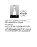
INSTALLING THE ID SIXTY
Before mounting the ID Sixty control head, gather the parts you need: ID Sixty, mounting
hardware kit, power cable, and transducer cable. If the transducer cable is not long enough for
your installation, see “Accessories” earlier in this manual for information on the EC-6-10 foot
extension cable.
Next, consider where to mount the ID Sixty. To choose the best location, consider the following:
•
The mounting area should allow at least 2” clearance around the back of the unit for
connection, air flow, and ease of removal.
•
Any VHF radio you have may incur some degree of interference with the depth sounder.
Hummingbird depth sounders are designed to minimize this interference, although it is best to
route the transducer cable and antenna cable as far away from each other as possible, for
example, on opposite sides of the boat.
After you have determined the best location for your ID Sixty, pr0ceed with the following
instructions.
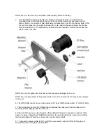
1. Drill a 3.5’ hole to accommodate the control head.
NOTE: 3.5” hole saws are readily available at most hardware stores. If you do not want to but a
saw for this purpose, tool rental stores or marine dealers may be another source.
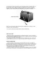
2. From the front, place the unit into the 3.5” hole.
Summary of Contents for ID Sixty
Page 1: ......