background image

 
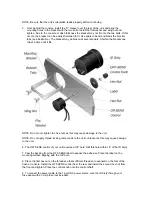
NOTE: Be sure that the unit’s orientation reads properly before continuing. 
 
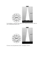
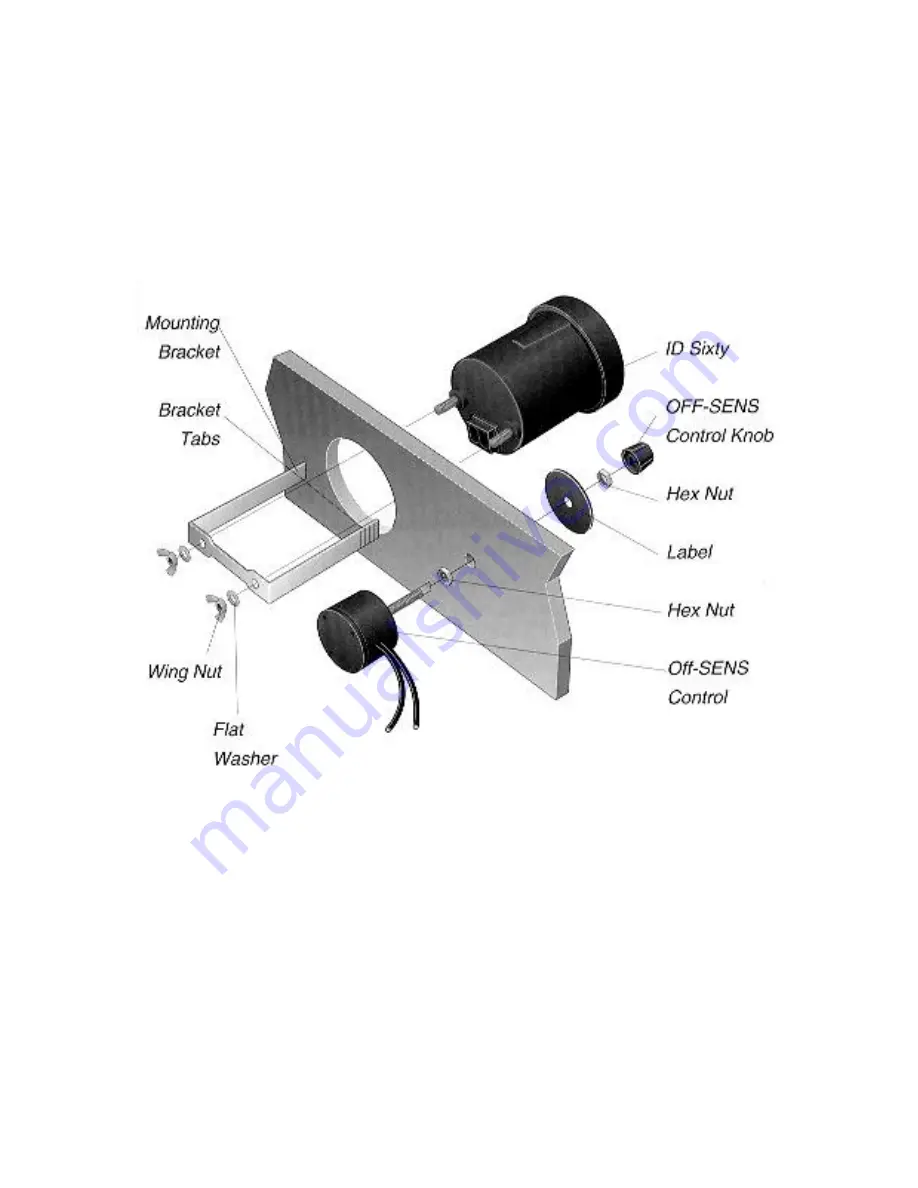
3.  From behind the console, install the “U” bracket over the rear of the  unit and align the 

mounting holes in the bracket with the two bolts. Install the flat washer and wing nut and 
tighten. Due to the console or dash thickness the bracket may not fit onto the two bolts. If this 
occurs, the bracket can be easily shortened to fit. Use pliers to bend and break the bracket 
tabs (see illustration). The bracket may be broken at several points. Shorten the bracket one 
tab at a time until it fits.   


NOTE: Do not over tighten the hex nuts as this may cause damage to the unit. 
 
NOTE: Do not apply thread locking compounds to the unit or bracket as this may cause damage 
to the unit. 
 
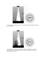
6. The OFF-SENS control of your unit requires a 3/8” hole. Drill this hole within 18” of the ID Sixty. 
 
7. Peel the backing from the OFF-SENS label to expose the adhesive. Place the label on the 
mounting surface aligning with the 3/8” hole.   
 
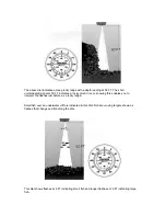
8. Place the first hex nut on the threads so that sufficient threads are exposed on the font of the 
dash or console. Install the OFF-SENS control from the rear and install the second hex nut from 
the front and tighten. Place the control knob onto the control shaft. 
 
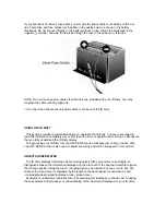
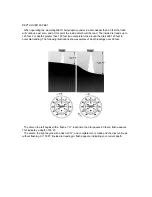
9. To connect the power cable to the 12-volt DC power source, wire the ID Sixty through your 
fuse panel with a 1-amp fuse (not included). 

Summary of Contents for ID Sixty

Page 1: ......

Page 2: ...m the transducer to the reflecting object and back again This time is then converted into feet and the number of feet to the object is indicated on the calibrated dial with the spinning lamp The lamp...

Page 3: ...control head gather the parts you need ID Sixty mounting hardware kit power cable and transducer cable If the transducer cable is not long enough for your installation see Accessories earlier in this...

Page 4: ...n the hex nuts as this may cause damage to the unit NOTE Do not apply thread locking compounds to the unit or bracket as this may cause damage to the unit 6 The OFF SENS control of your unit requires...

Page 5: ...arn to use your depth sounder Doing so will ensure that you fully understand the ID Sixty display To begin using your ID Sixty turn the OFF SENS control clockwise just until you hear a click The OFF S...

Page 6: ...dial indicates a rocky bottom with a depth of 30 FT as shown in the illustration Notice the short uninterrupted depth signal at 30 FT A hard clay sand and gravel bottom at 35 FT is represented on this...

Page 7: ...signal is uninterrupted and has increased in length This dial indicates a soft bottom with vegetation as shown in the illustration The depth is indicated at 50 FT with an uninterrupted signal Vegetati...

Page 8: ...round cover knowing this enables you to interpret the flashes just before as a rocky ledge Small fish over an underwater cliff are indicated in this dial Fish are moving targets shown as flashes that...

Page 9: ...o complete turns around the dial add 120 feet to outer dial reading The following illustrations show examples of depth readings over 60 feet The dial on the left begins with a flash at O Each time the...

Page 10: ...and any other electronic device that may cause interference Turn the OFF SENS control just past the click The dial should signal at O feet dial 1 Turn the control clockwise as needed to get a good la...

Reviews: