background image


Storing a Position (Waypoint) 

 
Storing a position, or waypoint, is helpful in tracking areas of interest or marking points for 
navigation. You may store up to 250 permanent waypoints and 50 temporary waypoints. 
Permanent waypoints are retained in permanent memory; temporary waypoints are not and will 
be lost when the NS25 is turned off. Several options for creating waypoints are available with the 
NS25. 
 
Pressing P-Stor instantly stores your present position, with depth of water information. A Store As 

menu Displays to provide the option to save it as Temporary or Permanent. 


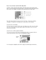
Pressing P-Stor while the Cursor is on-screen stores the position of cursor. The Store As menu 

provides the option of saving a Temporary or Permanent waypoint.  


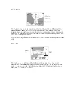
Using the Create Waypoint option in the Main Menu also stores waypoints and saves them to the 
Permanent waypoint list. Using the menu system you can enter precise coordinates for a  
waypoint and immediately assign a name and symbol. 
 
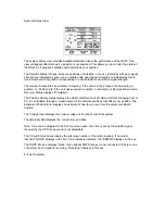
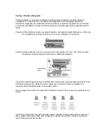
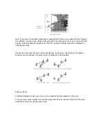
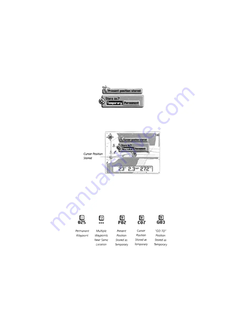
Once a waypoint is stored, the waypoint is indicated on-screen by one of several symbols shown 
below. 


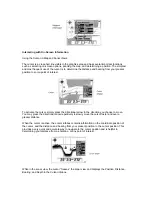
Information stored with a waypoint includes position, distance, bearing, date created, number of 
times vi sited. Visits accrue each time a waypoint is visited using GOTO.  Depth is also saved 
when storing your present position. 


Summary of Contents for NS25

Page 1: ......

Page 2: ...obal Positioning Systems DGPS which operate to refine satellite signal to the most accurate position possible GPS uses a constellation of 24 satellites that continually sends radio signals to the eart...

Page 3: ...mended that you install the NS25 components in the following order 1 GPS receiver 2 transducer 3 card reader then 4 control head GPS Receiver Installation To optimize performance of the GPS receiver m...

Page 4: ...Less Than 3 8 Follow these steps to deck mount the GPS receiver routing the cable down through the mounting surface 1 Determine the best location then route the 20 foot cable from control head to mou...

Page 5: ...ting holes for drilling 3 Remove flange and drill holes using a 9 64 drill bit 4 Break out the marked tab on the bottom side outer rim of the flange 5 Preassemble the flange mounting bolt and gasket w...

Page 6: ...our number listed in the Customer Support section INSTALLATION OVERVIEW Your Humminbird fishfinder consists of two primary components to install the control head and the transducer The control head c...

Page 7: ...should the boat strike debris in the water or when trailering As an alternative to transom mounting it is possible on many fiberglass hulled boats to glue the transducer on the inside of the boat hull...

Page 8: ...other surface Trolling Motor Mounting The standard transducer can also be adapted to mount on most trolling motors using a different accessory kit This accessory includes a bracket and hose clamp that...

Page 9: ...minbird fishfinder The installation guide included on the next few pages provides detailed step by step instructions for installation of the control head and transducer For transom mount transducer in...

Page 10: ...the propeller s This turbulent water is normally confined to areas immediately aft of ribs strakes or rows of rivets on the bottom of the boat and in the immediate area of the propeller s Figure 1 On...

Page 11: ...g a 5 32 4mm bit drill the two holes to a depth of approximately 1 3cm On fiberglass hulls it is best to start with a smaller bit and use progressively larger drill bits to reduce the chance of chippi...

Page 12: ......

Page 13: ...urther adjustment may be necessary to refine the instillation after high speed testing 1 First adjust the pivot angle of the transducer body so its length is parallel with the length of hull of the bo...

Page 14: ...mounting bracket Drill this hole and install the screw after final testing and adjustments have been completed...

Page 15: ...erference If the cable is too short extension cables are available to extend the transducer cable up to a total of 50 15 m Call Humminbird Customer Support for more information Follow these steps to r...

Page 16: ...unting Location Begin the transducer installation by determining where inside the hull to install the transducer Consider the following to find the best location Observe the outside of the boat hull t...

Page 17: ...The transducer cannot transmit through air The water purges any air from between the transducer and the hull and fills any voids in the coarse fiberglass surface...

Page 18: ...dry the mounting surface If the surface is excessively rough it may be necessary to sand the area to provide a smooth mounting surface Ensure the mounting area is clear and dry 3 Mix an ample quantit...

Page 19: ...supplied hole cover The mounting surface should be adequately supported to protect the fishfinder from excessive wave shock and vibration and provide visibility while in operation The mounting area sh...

Page 20: ...fuse in the connection If you must wire the control head directly to a battery be sure to install an inline fuse holder...

Page 21: ...mounting surface mark and drill a 1 25mm hole centered between the four mounting holes Figure 22 Note if the cables must pass through the mounting surface at a different location drill the 1 25mm hol...

Page 22: ...Optional If the cables pass outside the mounting bracket install the hole cover over the hole and fasten in place using the two 8 x 7 8 22mm wood screws Figure 24...

Page 23: ...ll the excess cable from beneath the mounting surface so the connector holder aligns with the mounting holes on the front of the mounting bracket Figure 27 3 Snap the support plate to the rear of the...

Page 24: ...rmal operation unless you choose another option If you do not press any button before the timer reaches 0 the normal operation screen is displayed If the boat is in water sonar data appears If the bot...

Page 25: ...position use 1 screws to mark hoes for mounting then remove card reader and drill holes using a 9 64 drill bit 3 Align card reader with drill holes secure to surface with 8 x flat head philips screws...

Page 26: ...beacons etc display in the map view The card reader equipped with the NS25 holds two C Cards simultaneously and automatically detects which one to use while you are navigating The NS25 cannot recogni...

Page 27: ...tronics particularly VHF radios route the transducer cable and the antenna cable as far apart as possible A separate power source may be necessary to eliminate interference Before installation gather...

Page 28: ...ess the latch on the rear of the unit and separate the unit from the mounting bracket 2 Set the mounting bracket on the mounting surface 3 Mark the four mounting screw locations with a pencil or punch...

Page 29: ...the mounting surface aligned with the drilled holes Insert the four flat head wood screws into the mounting holes and tighten fully Optional If the cables pass outside the mounting bracket install the...

Page 30: ...and lift Your NS25 unit is now ready for operation Testing The Installation GPS Testing Check System Status screen to confirm the unit is picking up satellite signals shown in Satellite Status box On...

Page 31: ...stment Start Up The NS25 is completely automatic and easy to use Simply press the POWER button and select Start Up This mode determines your position and displays it on a map tracks the bottom from 2...

Page 32: ...W to highlight Simulator When the screen times out the unit will be in simulator mode To exit simulator mode turn the unit off Demonstration Operation The NS25 has a demonstration function that works...

Page 33: ...map range Menu Displays the Main Menu Bar list and toggles through each of the five menu options Go To Initiates navigation to a destination Info Displays detailed information for highlighted waypoin...

Page 34: ...card and your area of operation More detailed map ranges will be available in some areas and less detail in others All views can be customized to display more or less detailed numeric and graphic inf...

Page 35: ...course projection deviates more than 10 degrees the map redraws your new course at the top of the screen If you are not moving the NS25 cannot determine a course and will show the map oriented to the...

Page 36: ...precise information for navigating to waypoints In the Numeric View a strip compass appears at the top of the display to graphically depict your course Digital readouts provide depth speed and course...

Page 37: ...eiver Status displays Simulation The Position Quality status displays the Horizontal Dilution of Precision HDOP Ranging from 0 99 it is calculated through a measurement of the satellite positions that...

Page 38: ...e it as Temporary or Permanent Pressing P Stor while the Cursor is on screen stores the position of cursor The Store As menu provides the option of saving a Temporary or Permanent waypoint Using the C...

Page 39: ...tional arrow in the direction you choose to move You may press the directional arrow repetitively to slowly move the cursor faster and over a greater distance When the cursor is active the cursor info...

Page 40: ...pends on the cartridge you are using and the area of operation Using the Cursor to Pan the Map The cursor may also be used to scroll the map on the display screen When the cursor reaches the border of...

Page 41: ...artography Icons appear on the maps displaying the locations of lights buoys and other man made features as well as natural areas such as tideways current zones and sea bottom conditions Moving the cu...

Page 42: ...and infoboxes Making adjustments can quickly add or eliminate objects on screen to reduce clutter Highlighting fewer numbers in the menu displays less information highlighting more numbers displays mo...

Page 43: ...e bottom of the screen to provide you navigation and position information You may customize each view individually to display any or none of the following numeric information The following numeric inf...

Page 44: ...l waypoint is reached Estimated Time of Arrival ETTA Approximate time of day you will arrive at a destination Track TRK Angle of line connecting starting and ending waypoints Measured from north 000 d...

Page 45: ...or Spot Soundings To Assign Information Priority Levels 1 Press INFO the Info Options screen displays 2 Scroll to Assign Information Priority Levels then select Yes 3 The Objects screen displays scro...

Page 46: ...tion and pressing GOTO adds successive waypoints to the route Creating a Route Using the GOTO Button First Pressing GOTO displays a list of options for creating a route If you know position coordinate...

Page 47: ...screen to provide navigation information to the destination waypoint These boxes are characterized by white text on black Navigation infoboxes can be customized for each view to show only the informa...

Page 48: ...formation appears on the North Up Course Up Combo Sonar and Numeric Views The View you select depends on your situation and personal preference The North Up view displays all navigation information re...

Page 49: ...ap ranges the proximity of the course projection line to the track line indicates how accurately the course is being followed The Combo view displays the North Up map and sonar information useful for...

Page 50: ...nm This can be adjusted manually see Using the Menu System Alarms for mire information Waypoint Sequencing as you move beyond a destination waypoint within the route the NS25 automatically sequences t...

Page 51: ...o modify route menu displays for chanding the route Choose the option from the menu which changes the route as you need Refer to the figures below for exact examples of how the route is modified for e...

Page 52: ...to 250 permanent waypoints and 50 temporary lost at power off waypoints The waypoint menus allow you to navigate to watpoints and list create change or delete waypoint information Pressing CLEAR when...

Page 53: ...er appropriate numbers then select OK when finished Note Using the Clear or Menu key to exit at this point will save waypoint information 4 The Enter Name menu displays Scroll through letter fields to...

Page 54: ...series of waypoints together to create a path that can be saved and used later They are comprised of 2 to 50 waypoints and can be traveled in whole or in part in either direction There are two types...

Page 55: ...e select Add 1 to determine this as the first waypoint Continue adding waypoints in sequence until you reach the last one for your route For the last waypoint select End this displays t he Enter Name...

Page 56: ...ms alerting you to conditions such as off course navigating destination arrival position drifting shallow water and fish The current setting for the alarm displays in the upper right corner of the ala...

Page 57: ...ivate the alarm The factory setting is 1NM 3 Select Adjust to change the numeric alarm setting 4 The Adjust Drift Alarm menu displays Scroll to a setting from 01NM to 1NM Note the alarm setting is sav...

Page 58: ...ss of the screen to accommodate for outdoor lighting conditions To set Display Contrast 1 Highlight Display Contrast 2 Elect desired setting from 5 to 5 The factory setting is zero Units Speed Units S...

Page 59: ...ich your position is displayed To set Coordinate System 1 Highlight Coordinate System 2 Select appropriate coordinate format The dd mm mmm setting is the factory setting If Loran TD s is selected then...

Page 60: ...cally this setting does not need to be adjusted To set Map Datum 1 Highlight Map Datum 2 Select the datum for the map the factory setting is WGS 84 If Custom is selected then select Set Up The custom...

Page 61: ...level 1 7 Continue scroll through the objects list to prioritize objects for display according to your preference Land Water Land Water inverts the colors for land and water on screen To set Land Wat...

Page 62: ...used to generate the digitized maps Entering an off set distance with respect to your position moves the map to the correct position To set Map offset 1 Highlight Map Offset 2 Select On then Adjust Y...

Page 63: ...nd routes stored in memory To Delete All Waypoints 1 Highlight Delete All Waypoints 2 Select Yes to delete all waypoints and routes Simulator Location Simulator Location sets the center point of the s...

Page 64: ...is compatible with DGPS Differential Global Positioning System which uses radio tower signals to enhance position accuracy These signals are available in select areas check your area of operation for...

Page 65: ...cklight Electroluminescent EL Mounting Quick Disconnect or In Dash Construction High Impact Polycarbonate with Silicone Gasket Dimensions 7 5 8 h x 7 7 8 w x 4 3 8 d GPS Receiver Channels 12 Parallel...

Page 66: ...0 Temporary Routes 20 Permanent 10 temporary Course History 1000 Points Power Voltage Input 10 16 VDC In Line Fuse 1 5 Amp Slow Blow Power Consumption 4 5 watts 13 VDC Backlight Off 7 watts 13 VDC Bac...

Page 67: ...ate position readout DD degrees MM SS Selects position readout in Latitude Longitude showing degrees DD degrees minutes MM and seconds SS This is the traditional but less precise method of coordinate...

Page 68: ...ere are two options available for the display of your position LAT LON is the default setting it provides your position with reference to the standard coordinate positioning of latitude and longitude...

Page 69: ...om Loran stations UTM Selects position readout in Universal Transverse Mercator the coordinate system used by some maps such as USGS topographic maps WAYPOINT A point of interest stored and included i...

Page 70: ......

Page 71: ......

Reviews: