S
TEP
3: D
ETERMINE
C
ONTROL
H
EAD
M
OUNTING
L
OCATION
When choosing a mounting location consider the following:
• Power and transducer cables should be installed first and must reach the control
head. Transducer extension cables are available. The power cable can be
shortened or lengthened with 18 gauge wire.
• If possible, choose a location that provides access from below so above deck
cable length is short, and the cable’s hole can be covered by the mount base.
• Ensure enough space exists for easy control head installation and removal and for
pivoting through its full range of motion.
• The mounting area should be well supported to protect the fishfinder from wave
shock and vibration.
• Choose an area that provides good visibility for the Piranha.
S
TEP
4: E
LECTRICAL
C
ONNECTIONS
A 6’ (2m) long power cable is included to supply power to the fishfinder. You may short-
en or lengthen the cable using 18 gauge multi-stranded copper wire.
CAUTION: Some boats have 24 or 36 volt electric systems. Be sure your
unit is connected to a 12 VDC power supply. Humminbird is not
responsible for over current or over voltage failures.
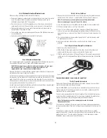
The power cable can be connected to the boat’s electrical system at two places: a fuse panel, usu-
ally located near the console, or directly to the battery.
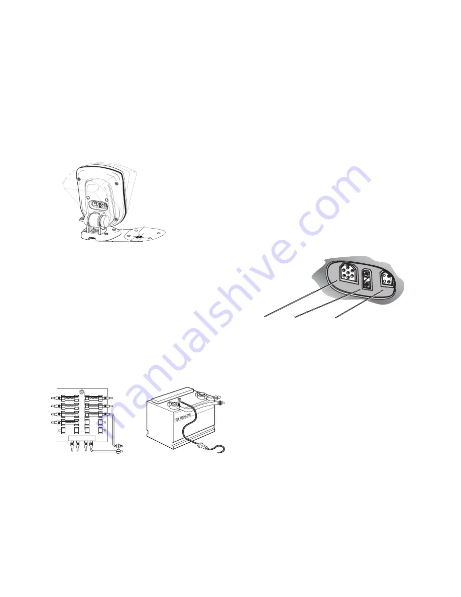
If a fuse terminal is available, use crimp-on type electrical connectors (not included) that match
the terminal on the fuse panel. Attach the black wire to ground and the red wire to 12 VDC
power (Figure 10). Be sure to use a one amp fuse in the connection. If you must wire the con-
trol head directly to a battery, be sure to install an inline fuse holder and use a one amp fuse
(not included) for the protection of the unit (Figure 11).
In order to minimize the potential for interference with other marine electronics a separate power
source (such as a second battery) may be necessary.
S
TEP
5: I
NSTALL THE
B
ASE
1. Remove the control head from the mount base by loosening the gimbal knob and
pulling the unit from the base - a slight twisting motion will help to release it.
Note: It is not necessary to completely remove the gimbal knob.
Unscrew only enough to permit the unit to release.
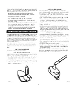
2. Using the mount base as a template, mark the location for the mounting holes.
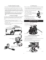
3. Drill the mounting holes using a
⁹⁄₆₄
" (3.6mm) bit.
4. Drill a
⁵⁄₈
” hole at the location where the cables pass through the mounting
surface. If access is possible underneath mounting surface, drill the hole so the
mount base forms a hole cover. See Figure 9 for location of cable hole under the
mount.
5. Pass the transducer and power cables through the
⁵⁄₈
" inch hole, leaving about
6” length above the surface.
6. Align the mount base with the holes and attach with the Phillips screws
provided.
S
TEP
6: A
TTACH THE
C
ONTROL
H
EAD AND
P
LUG
I
N
C
ONNECTORS
1. Mount the control head to the base.
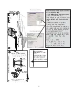
2. With attention to shape and orientation of the plugs, insert the transducer and
power cable into the correct socket according to the figure at right.
3. With the control head in place, tilt the unit through its full range to ensure enough
cable slack is left for movement. Hand tighten the gimbal knob when at its desired
position.
Your new Humminbird is now ready for operation!
T
EST
& C
OMPLETE
I
NSTALLATION
Testing should be performed with the boat in the water, however, you can initially
confirm basic operation with the boat trailered.
Press POWER-MENU once to turn the unit on. An audible chirp sounds any time a
button is pressed. If the unit does not power on, ensure the cable plugs are fully
seated and there is power available.
The first screen indicates either Start-Up and Simulator. If the unit detects the transduc-
er, Start-Up will be the default selection. If no transducer is detected, Simulator will be
selected. Use the Arrow keys to change between Start-Up and Simulator.
Note: The transducer must be submerged in water for reliable
transducer detection.
If the transducer is detected, after several seconds the Piranha will begin operation unless
you choose another option. If the boat is in the water sonar data begins to scroll across the
screen.
If the bottom is visible on-screen with digital depth readout the unit is working
properly. If no bottom is visible or erratic operation occurs, ensure that the unit is in
water greater than 3' (1 meter) and the transducer is fully submerged in water.
Remember, sonar signals can not travel through air.
⁵⁄₈
"
Figure 9
Cabling can be routed
through a
⁵⁄₈
" hole
centered between the
two rear mounting
holes of the base.
GROUND
POSITIVE
Figure 10
Figure 11
Transducer
Power
Temperature
3