If the unit is working properly, gradually increase boat speed to test higher speed
performance. If the unit functions well at low speeds but begins to skip or miss the
bottom at higher speeds, the transducer requires adjustment.
Note: Transducer installation often requires several incremental
adjustments before optimum high-speed performance is achieved.
To optimize transducer installation, try the following.
• Ensure the transducer is NOT located in an area of turbulent water.
• First, incrementally lower the running depth by
¹⁄₁₆
" until best high-speed
performance is achieved.
• If the bracket is fully extended and high-speed performance continues to need
adjustment, incrementally change the Pivot Angle to lower the rear of the
transducer by
¹⁄₈
" steps until best high-speed performance is achieved.
Important: For transom mount transducers, install the third mounting
screw after final transducer adjustments. Hand tighten only!
O
OPTIONAL INSIDE HULL TRANSDUCER MOUNTING
Inside the hull installation requires the control head to be installed and operational. Inside the
hull mounting generally produces good results in single thickness fiberglass-hulled boats.
Humminbird cannot guarantee depth performance when transmitting and receiving through the
hull of the boat, since some signal loss occurs. The amount of loss depends on hull con-
struction, hull thickness and the installation. In addition, the temperature probe is embedded in
the transducer, therefore, temperature readings will be hindered unless a second transom
mounted temperature probe is used.
This installation requires slow-cure two-part epoxy. Do not use silicone or any other
soft adhesive to install the transducer, as this material reduces the sensitivity of the
unit. Five minute epoxy has a tendency to cure before all the air bubbles can be
purged.
S
TEP
1: I
NSTALL THE
C
ONTROL
H
EAD
Follow directions above for installing the control head.
S
TEP
2: D
ETERMINE THE
M
OUNTING
L
OCATION
Begin the transducer installation by determining where inside the hull to install the
transducer. Consider the following to find the best location:
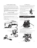
• Observe the outside of the boat hull to find the areas that are mostly free from
turbulent water. Avoid ribs, strakes and other protrusions as these create
turbulence (Figure 2).
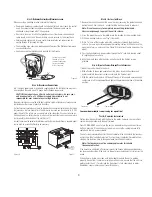
• As a general rule, the faster the boat can travel, the further aft and closer to the
centerline of the hull the transducer has to be located to remain in contact with
the water at high speeds (Figure 13).
S
TEP
3: T
EST THE
M
OUNTING
L
OCATION
There is no opportunity for adjustment after the transducer is glued in place.
Therefore, it is best to perform a trial installation on inside the hull transducers first,
and run the boat at high speeds to determine the best mounting area.
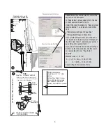
1. At the identified mounting location, lay the transducer body face down with the
pointed end towards the bow.
2. Fill the hull with enough water to submerge the transducer body. Use a sand
filled bag or other heavy object to hold the transducer in position.
The transducer cannot transmit through air. The water purges any air from
between the transducer and the hull, and fills any voids in the coarse fiberglass
surface.
3. Power up the Control Head.
4. Run the boat at various speeds and water depths while observing the screen on the
Control Head. If the unit functions well at low speeds but begins to skip or miss the
bottom at higher speeds, the transducer needs to be moved. If depth performance is
required, test the fishfinder in water at the desired depth. Test different locations in the
hull until the optimum performance is achieved.
S
TEP
4: P
ERMANENTLY
M
OUNT THE
T
RANSDUCER
1. Once the mounting location is determined, mark the position of the transducer.
2. Remove the water from inside the hull and thoroughly dry the mounting surface.
If the surface is excessively rough, it may be necessary to sand the area to
provide a smooth mounting surface.
Ensure the mounting area is clean and dry.
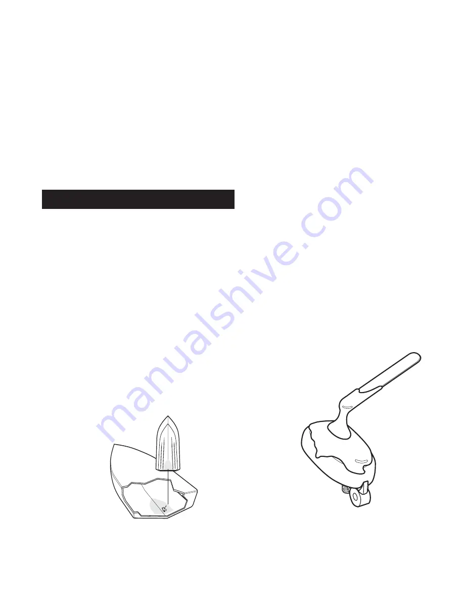
3. Mix an ample quantity of two-part slow-cure epoxy slowly and thoroughly. Avoid
trapping air bubbles.
4. Coat the face of the transducer and the inside of the hull.
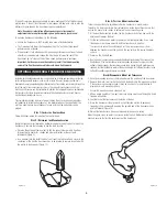
5. Press the transducer into place with a slight twisting motion to purge any
trapped air from underneath, keeping the pointed end of the transducer body
pointed forward (Figure 14).
6. Weight the transducer so it does not move while the epoxy is curing.
When the epoxy cures, no water is necessary inside the hull. Neither water, spilled
gasoline, nor oil will affect the performance of the transducer.
Figure 13
Figure 14
4