The following describes the functions and how to use them, in order of appearance after you turn
the unit on.
1.
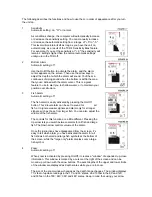
Sensitivity
Automatic setting: on, "O" or normal
As conditions change, the computer will automatically increase
or decrease the sensitivity setting. You can manually increase
or decrease the automatic setting from a range of "+5" to "-5."
This level will maintain itself as long as you have the unit on,
automatically, as a result of the TCR's Sensitivity Bias feature.
For example, if you set the sensitivity at "+2," the sensitivity will
remain 2 settings higher than the normal automatic settings
until you turn the TCR off.
2.
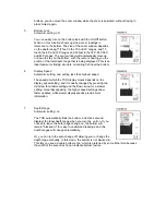
Bottom Alarm
Automatic setting: off
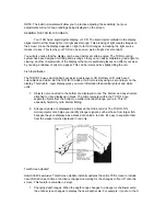
Use the On/Off button to activate the alarm, and the alarm
cursor appears on the screen. Then use the arrow keys to
adjust the depth at which the alarm will sound. You'll hear a
continuous chirping sound when the bottom is within the area
that you've defined with the alarm cursor. This is a great
feature to use to alert you to shallow water, or to maintain your
position over structure.
3.
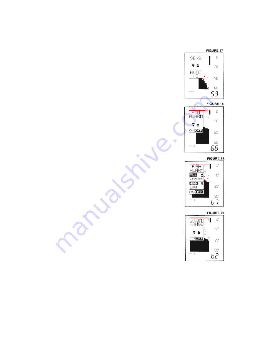
Fish Alarm
Automatic setting: off
The fish alarm is easily activated by pressing the On/Off
button. This 2-level alarm can be set to sound for
all
fish, or to ignore weaker signals and alarm only for stronger
signals, such as those from larger fish. You can also adjust the
volume of the fish alarm.
The controls for this function are a little different. Pressing the
Up arrow lets you switch between alarms for all fish and large
fish. The Down arrow controls volume of the alarm.
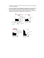
Once the instructions have disappeared from the screen, it's
easy to tell which alarm you have activated-the alarm for all
fish shows both small and large fish symbols at the bottom of
the screen, while the "large only" alarm displays only a large
fish symbol.
4.
Zoom
Automatic setting: off
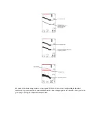
When zoom is activated by pressing On/Off, it creates a "window" of expanded, up-close
information. This window is marked by a cursor at the right of the screen and can be
moved up or down with the arrow buttons. The exact depths of the upper and lower limits
of the window are displayed as depth scales while you are in zoom.
The size of the zoom window changes as the depth range changes. The window displays
71/2 feet of upclose readings in the 15' and 30' scales, and 15 feet in the 60' and 120'
and 30 feet in the 180', 240', 360' and 480' scales. Keep in mind that, using your arrow