background image

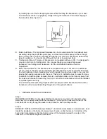
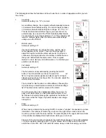
7.  Remove the water and transducer and clean the marked area and the bottom of the 

transducer thoroughly. 

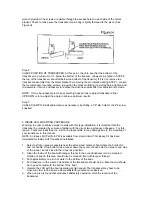
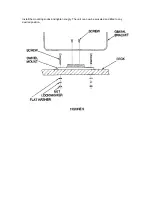
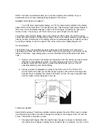
8.  Using the Humminbird Epoxy Kit or equivalent, mix an ample amount of epoxy without 

causing it to bubble and pour it in the area the transducer is to be mounted. The puddle 
should be larger than the bottom of the transducer. 

9.  Coat the bottom of the transducer with epoxy, then put it in the center of the puddle and push 

down on the transducer while moving it around in a circular motion. This forces out any air 
bubbles that may be trapped between the bottom of the transducer and the hull of the boat. 

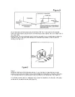
10.  Let epoxy cure then the transducer is ready to operate. No water is now required in the 

bottom of the boat and gas and oil that is spilled inside of the boat will not degrade 
performance as it will if the transducer is placed only in water. 
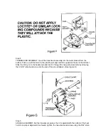
CAUTION: Do not use the silicone seal or any soft adhesive to bond the transducer to the 
hull. This will reduce the sensitivity of the unit. 


CAUTIONS 
1.  Occasionally the “eye“ of your transducer may become dirty from storage or from contact with 

oils present in boats or marina environments. (Oil will cause the “eye” to  lose the intimate 
contact with the water which is necessary for efficient operation.) The “eye” may be cleaned 
with liquid detergent.  

2.  Improper installation of the transducer can alter the efficiency and accuracy of the entire 

system. 

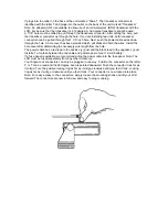
3.  If your boat of transducer is out of the water for a period of time, it may take a short period of 

time for the transducer to become thoroughly “wetted” when returned to the water. Also, re-
entry may cause turbulence, which will create air bubbles in the “eye” of the transducer. The 
bubbles will disappear in a short time or can be removed by rubbing the transducer “eye” with 
your fingers while the transducer is in the water. 

4.  If your instrument should fail to function, be sure to check all the electrical connections before 

removing the transducer or calling a serviceman. 

5.  Inspect your transducer cable and make sure that it has not been cut or damaged to the point 

where it will affect the performance of the transducer. A slight nick or cut, exposing the outer 
cable, can be repaired by wrapping with electrical tape. A transducer can be damaged if the 
inner cable and outer cable are allowed to make contact. Such a problem can  sometimes be 
corrected by properly splicing the coaxial cable. This should only be attempted by a qualified 
service technician. 

6.  If your LCR is not working properly and you suspect the problem might be in your transducer, 

we would recommend you borrow a unit from a friend and try it on your boat. If the symptoms 
are the same, you can almost be certain that the problem is in the transducer.   
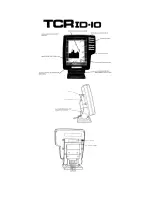
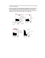
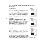


 INSTALLING THE LCR 
 
The LCR should be mounted on a flat, solid surface for maximum stability.  The low profile swivel 
mount has four holes drilled in the base. It is recommended that all four holes be used. 
 
Position the swivel base and drill four ¼” diameter holes. Note: The LCR hole pattern Is the same 
as for all Humminbird flasher units. Use hardware provided to mount this base to the boat. 
 
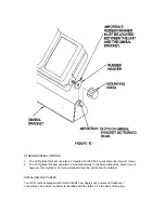
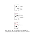
Next place the gimbal bracket on the swivel base and attach with four small machine screws, 
provided. 
Place the LCR in the gimbal mount and make certain the rubber washers provided are placed 
between the unit and the gimbal bracket Important: Note which side of the gimbal faces forward.  
(Slots on gimbal bracket go towards rear). Also, rubber washer must be located between the unit 
and the gimbal bracket. 
 

Summary of Contents for TCR ID-10

Page 1: ......

Page 2: ...luding aluminum Please carefully consider the following before installing your transducer TRANSDUCER MOUNTING OPTIONS A Transom Mount The Humminbird high speed transducer allows the transducer element to be mounted below the bottom of the boat hull keeping the transducer out of turbulent water and insuring good high speed operation The transducer will absorb the blow of any obstruction ...

Page 3: ...e bronz thru hull transducer has a threaded stem which installs through a hole drilled in the boat hull leaving the housing exposed under the boat This type of installation must be used for many boats with in board engines because there is no suitable location on the transom away from the noise and turbulence created by the prop A bronz thru hull transducer should be installed by qualified personn...

Page 4: ...o use a silicone sealant between the screwhead and bracket in order to prevent leaking See Figure C Step 2 BRACKET INSTALLATION Fiberglass Boats If your boat has a stepped transom located below and under the main transom the compact transducer design allows mounting in this area This mounting location is recommended for good reading at very high speeds See Figure D To install the metal bracket on ...

Page 5: ...ically in the three slots found in the bracket It is important to use a silicone sealant between the screwhead and bracket in order to prevent leaking Step 3 TRANSDUCER PIVOT ASSEMBLY Assemble the pivot to the transducer main body using the two x5 8 allen head screws two 3 8 tooth washers and two square nuts Make sure the tooth washers are sandwiched between the transducer main body and the pivot ...

Page 6: ... the bracket Slide the O ring on to the headed pin and insert it through the two parts Assemble by screwing the x3 8 allen head screw into the end of the pin and tighten See Figure G Step 5 ANGLE ALLIGHMENT Set the transducer angle so that it is parallel with the bottom of the boat hull Once proper alignment is achieved tighten the two allen head screws using the 5 32 allen ...

Page 7: ...th this type installation it is important that the transducer be mounted by someone familiar with the use of two part epoxy adhesives For this reason Techsonic Industries Inc will not be responsible for any damage due to the mounting of your transducer in this manner NOTE An Epoxy Kit Part N EPK is available from Humminbird This Epoxy Kit has been formulated for Inside Hull Transducer Installation...

Page 8: ...eye of the transducer The bubbles will disappear in a short time or can be removed by rubbing the transducer eye with your fingers while the transducer is in the water 4 If your instrument should fail to function be sure to check all the electrical connections before removing the transducer or calling a serviceman 5 Inspect your transducer cable and make sure that it has not been cut or damaged to...

Page 9: ...Install the mounting knobs and tighten snugly The unit can now be swiveled and tilted to any desired position ...

Page 10: ...acket can also be mounted directly to the dash without the swivel mount however this method is not recommended since the unit cannot be rotated INSTALLING THE CABLES Your LCR comes equipped with Humminbird s new Angle Lock power and transducer connectors The power connector is identified with the letter P on the back of the plug ...

Page 11: ...hole cover after determining the necessary wire length from the hole The power cable has a red lead to the positive post and the black lead to the negative post Install a 1 amp fuse between the red cable and positive post of your 12 volt battery If a fuse panel is available we recommend wiring the power cable into the fuse panel Note The LCR must be fused separately from any other accessory Your A...

Page 12: ......

Page 13: ...e boat moves Your TCR ID 10 and its Transducer are designed to operate at up to 75 mph so feel free to test them at very high speeds If the TCR ID 10 performs well at idle or slow speeds but the display is not continuous at higher speeds then the Transducer is not installed properly Air bubbles or turbulence from the boat hull are passing across the face of the Transducer blocking the transmitted ...

Page 14: ...y LCD units have 2 colors black and white But the TCR ID 10 adds a third color red by using a second layer on the display This double layer display gives you more information than ordinary black and white units 1 Objects not connected to the bottom are displayed in red The bottom and any structure attached to it are displayed in black The microcomputer within the TCR I 10 can separate objects from...

Page 15: ... Memory Capacity the memory in the TCR ID 10 stores readings in much finer detail than is displayed in the regular mode So when you activate the zoom or bottom lock functions the entire screen changes to display the up close detail that is stored in memory Then when you turn off the zoom or bottomlock the whole screen will change back to the full depth scale ...

Page 16: ...e best way to learn to read your TCR ID 10 is to use it especially in familiar locations If you know what s underwater and can see it displayed on the screen then you re on your way to being an experienced TCR user ...

Page 17: ...r night vision Press the button again for a brighter light making the display easy to read at dusk when it can be harder to see Pressing the button a third time turns off the backlight Select System The TCR ID 10 Select System commands an amazing number of functions with only four buttons Select Up and Down arrows and On Off When you press the Select button each function appears in a block on the ...

Page 18: ...larm is easily activated by pressing the On Off button This 2 level alarm can be set to sound for all fish or to ignore weaker signals and alarm only for stronger signals such as those from larger fish You can also adjust the volume of the fish alarm The controls for this function are a little different Pressing the Up arrow lets you switch between alarms for all fish and large fish The Down arrow...

Page 19: ...ing one setting less than highest speed The speed at which the TCR display moves depends on the display speed setting and it is easily changed by pressing the Up arrow for a faster setting and the Down arrow for a slower setting Generally speaking the higher speed settings allow faster updates while slower display speeds provide more information 7 Depth Range Automatic setting on The TCR automatic...

Reviews:

Related manuals for TCR ID-10