background image

Table of Contents 


Package Contents ................................................................................................................ 4 

Product Overview ................................................................................................................. 5 

Features ............................................................................................................................... 6 

HTA-810/820/830/840 Comparison Table ............................................................................. 7 

Specifications........................................................................................................................ 8 

Physical Dimensions ............................................................................................................ 9 

Safety Precautions ............................................................................................................. 10 

Pictorial Introduction ........................................................................................................... 12 

Wiring Connections ............................................................................................................ 15 

RS-485 Wiring Connection ................................................................................................. 15 

RS-232 Wiring Connection ................................................................................................. 15 

TCP/IP RJ-45 Connection for HTA-830 .............................................................................. 16 

TCP/IP RJ-45 Connection for HTA-840 .............................................................................. 16 

Alarm Output Connection ................................................................................................... 17 

Communication Connection................................................................................................ 18 

Power Supply Connection .................................................................................................. 20 

Installation .......................................................................................................................... 21 

Troubleshooting .................................................................................................................. 22 

Appendix 1: Error Message Description ............................................................................. 23 


3

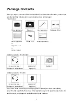
Summary of Contents for HTA-810

Page 1: ...Auto Manual Clock in and Clock out for HTA 820 830 840 Daylight Saving Control TCP IP Communication for HTA 830 840 Perfect for wall mount or desktop use Excellent for Payroll Management PoE Power ov...

Page 2: ...in order to improve reliability design or function The manufacturer will not be held responsible for technical or editorial omissions made herein nor for the incidental or consequential damages result...

Page 3: ...ecautions 10 Pictorial Introduction 12 Wiring Connections 15 RS 485 Wiring Connection 15 RS 232 Wiring Connection 15 TCP IP RJ 45 Connection for HTA 830 16 TCP IP RJ 45 Connection for HTA 840 16 Alarm...

Page 4: ...Barcode Cards x 3 Screws x 4 Quick Start Guide x 1 Additional items for HTA 810 820 DC Jack Converter x 1 If adaptor is not included Adaptor x 1 Optional Cable x 1 Additional items for HTA 830 DC Jack...

Page 5: ...0M HTA 820M HTA 830M HTA 840M Proximity Type HTA 810PE HTA 820PE HTA 830PE HTA 840PE HID Type HTA 810PH HTA 820PH HTA 830PH HTA 840PH Mifare Type HTA 810PM HTA 820PM HTA 830 PM HTA 840 PM To better se...

Page 6: ...HTA 810 820 HTA 830 840 uses TCP IP communication interface Visual LED for distant display of time card number last 4 digits and for communication mode swiped card indication Preset 16 time schedule f...

Page 7: ...s Keypad Backlight N A YES YES YES Re swiped card auto examine 0 255 sec 0 255 sec 0 255 sec 0 255 sec Clock in and Clock out N A YES YES YES Daylight Saving Control YES YES YES YES Preset 16 time sch...

Page 8: ...der Ports ABA Track 2 Wiegand26 x 1 Operating Voltage DC 12V 500mA DC 48V 57V Max 500 mA Power Consumption 3W max 5W 24W max Baud Rate 1200 2400 4800 9600 19200 bps N 8 1 default 9600 10Mbps Comm Inte...

Page 9: ...Physical Dimensions Front View Side View Back Base 9...

Page 10: ...th same characteristics as original part Unauthorized substitutions may result in fire electric shock or other hazards z Use only the metal housing specified supplied by the manufacturer to ensure com...

Page 11: ...k short circuit or it might burn the controller z Do not distort pull nor bend the power cable z Do not switch the power on off within a short period of time z Do not overload wall outlets extension c...

Page 12: ...840 3 Communication LED Red LED blinks upon receipt of data from PC Green LED blinks upon trasmission of data to PC 4 Swipe Card Indication LED Green LED blinks upon swipe of valid card Red LED blink...

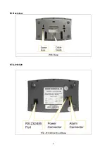
Page 13: ...Backview With Base HTA 810 820 HTA 810 820 without Base 13...

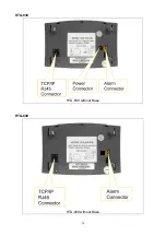
Page 14: ...HTA 830 HTA 830 without Base HTA 840 HTA 840 without Base 14...

Page 15: ...s RS 485 Wiring Connection Note Assign different IDs for each HTA 810 820 830 840 recorder when there are more than one recorder in the network Default ID is 1 Set your ID with our software RS 232 Wir...

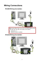
Page 16: ...TCP IP RJ 45 Connection for HTA 830 TCP IP RJ 45 Connection for HTA 840 16...

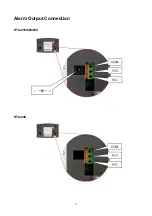
Page 17: ...Alarm Output Connection HTA 810 820 830 HTA 840 17...

Page 18: ...Communication Connection RS232 RS485 Communication Port for HTA 810 820 Communication Port for HTA 830 18...

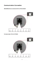
Page 19: ...Communication Port for HTA 840 Note POE stands for transmitting DC power 19...

Page 20: ...Power Supply Connection Note Power Supply Connection is for HTA 810 820 830 This is not applicable for HTA 840 as it uses PoE Power over Ethernet for its power supply 20...

Page 21: ...ount it onto the wall using the screws not required for desktop use Step 3 4 Align the extrusion part of the base to HTA 810 820 recorder s slots on the edges for base installation Step 5 6 Fasten the...

Page 22: ...840 make sure the IP port is correctly set Q I swiped the card but the device has no response A 1 Please check if the card format matches model purchased 2 Please make sure card registry process is c...

Page 23: ...Err2 Card number contains non numeric character under compression mode Err3 Cannot overwrite memory full Err4 Memory buffer 100 full Bad0 Flash configuration area damage Bad1 Flash valid card area da...

Page 24: ...ct This warranty does not cover damage due to improper operation or maintenance connection to improper equipment or attempted repair by anyone other than HUNDURE In no event shall HUNDURE s liability...

Reviews: