background image

7


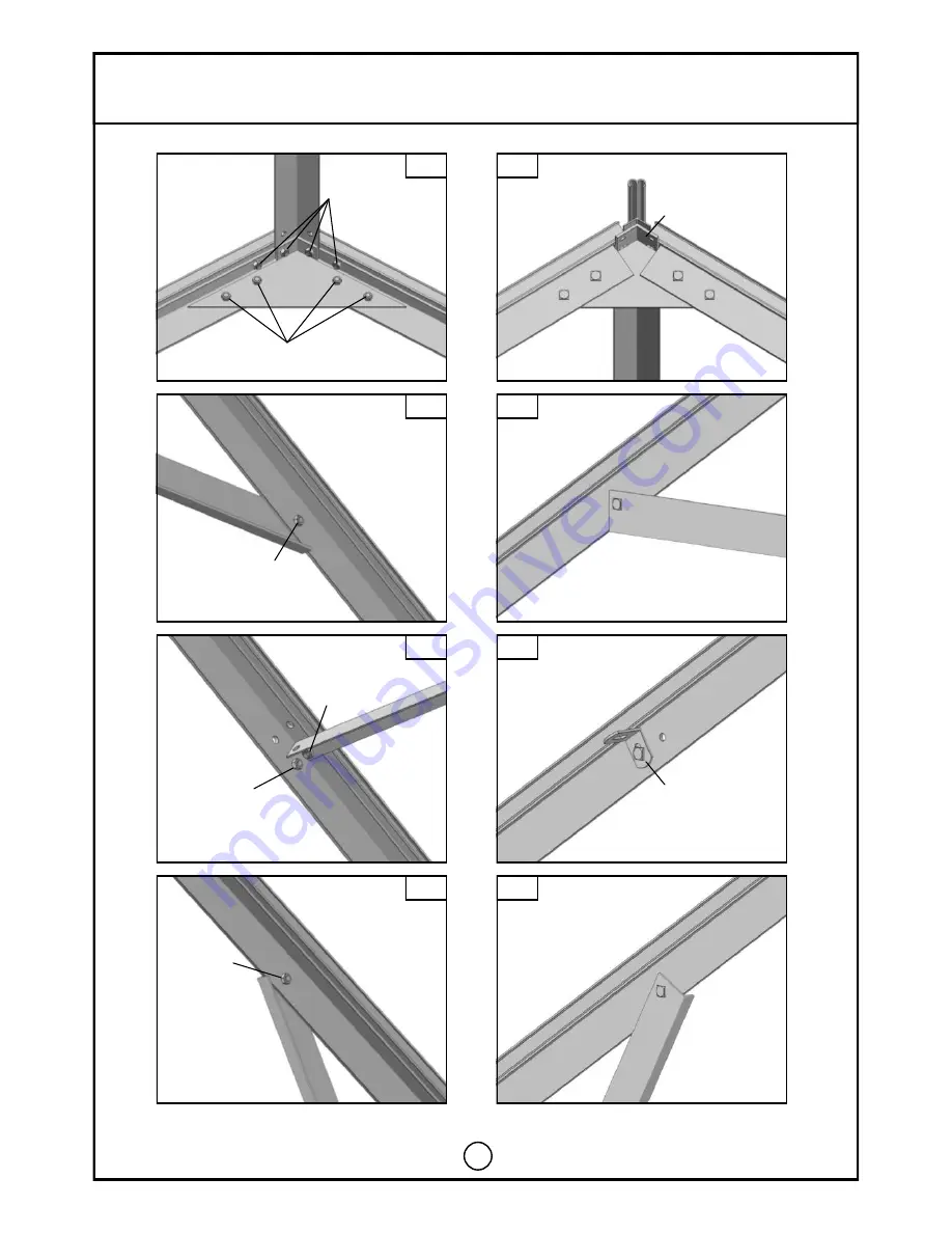
A-frame Layout


681


A


A-1


B


B-1


C


C-1


D


D-1


681


692


692


491


681


681


692


692


494


692


202


681


681


692


202


692


681


713


692


681


m6


692


202


681


202


692


681


a8/a2


a1/a2


a1/a2


a8/a2


a1/a2


a1/a2


Summary of Contents for Titan 912

Page 1: ...Titan 912 and 914 Extension ASSEMBLY INSTRUCTIONS To be used in conjunction with Titan 912 or Titan 914 instructions hunkin garden xnet co nz Ph 0800 14 48 65 ...

Page 2: ... 3 34 34 4 Polycarbonate sheet Size Qty c 1534 16 938 4 1570 12 s 660 30 f 12 72 1 2 3 4 Panel Panel Panel Assemble b5 Panel 5 SIDE b5 b5 b5 b5 B6 b7 B8 B6 c 1534 s 660 f 3 c 1534 c 1534 c 1534 c 1534 c 1534 c 1534 c 1534 s 660 f 3 s 660 f 3 s 660 f 3 s 660 f 3 s 660 f 3 s 660 f 3 s 660 f 3 s 660 f 3 s 660 f 3 s 660 f 3 s 660 f 3 s 660 s 660 c 1570 c 1570 c 1570 c 1570 c 938 c 938 B6 s 660 c 1570 ...

Page 3: ...3 Start with your completed greenhouse frame To add an extension unit disconnect the complete rear gable together with the base Put them aside for re attachment later ...

Page 4: ...4 8 16 24 8 8 First extend the extend the aluminium base as shown above a2 m7 Base crop bolts a2 Width Length Combination mm mm 2751 6319 one Titan 912 one HB9 extension 2751 7013 one Titan 914 one HB9 extension 2751 9095 one Titan 912 two HB9 extension 2751 9789 one Titan 914 two HB9 extension 4 ...

Page 5: ...er 10mm bolt in the top of the bar and angle it into the slot at the end of the gutter Place the gutter extension bracket over this 10mm bolt and lightly tighten Diagram E E 1 Repeat this on the opposite side 3 Now the roof bars 681 have to be installed These need the roof bar braces 692 attached to them in the same way as in step 1 Take one of the roof glazing bars with a 10mm bolt pre inserted i...

Page 6: ...6 A frame Layout front view rear view A B C A 1 B 1 C 1 681 202 202 202 692 666 666 694 694 D E F G D 1 E 1 F 1 G 1 ...

Page 7: ...7 A frame Layout 681 A A 1 B B 1 C C 1 D D 1 681 692 692 491 681 681 692 692 494 692 202 681 681 692 202 692 681 713 692 681 m6 692 202 681 202 692 681 a8 a2 a1 a2 a1 a2 a8 a2 a1 a2 a1 a2 ...

Page 8: ...8 A frame Layout E E 1 F F 1 G G 1 692 681 671 666 694 492 595 692 681 666 694 492 694 666 202 694 666 202 a8 a2 a1 a2 a1 a2 694 666 632 634 a8 a2 a1 a2 ...

Page 9: ...ry Important Bolts will need to be slid into each roof bar for the ridge brace and another for the longitudinal brace 716 One more bolt is needed to attach the eave bracing between the roof and the side Please note At this stage you will need to insert an extra bolt into each bar either side of a vent opening If you haven t already done so you need to decide now where your roof vents are going to ...

Page 10: ...10 Main Building With Extension Assembly H I ...

Page 11: ...11 Main Building With Extension Assembly J Main Building A Frame Extension Main Build ing Rear 672 666 753 681 J 1 J 2 J 3 J 1 J 2 J 3 681 681 681 716 702 751 752 ...

Reviews: