5
Rear Panel
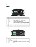
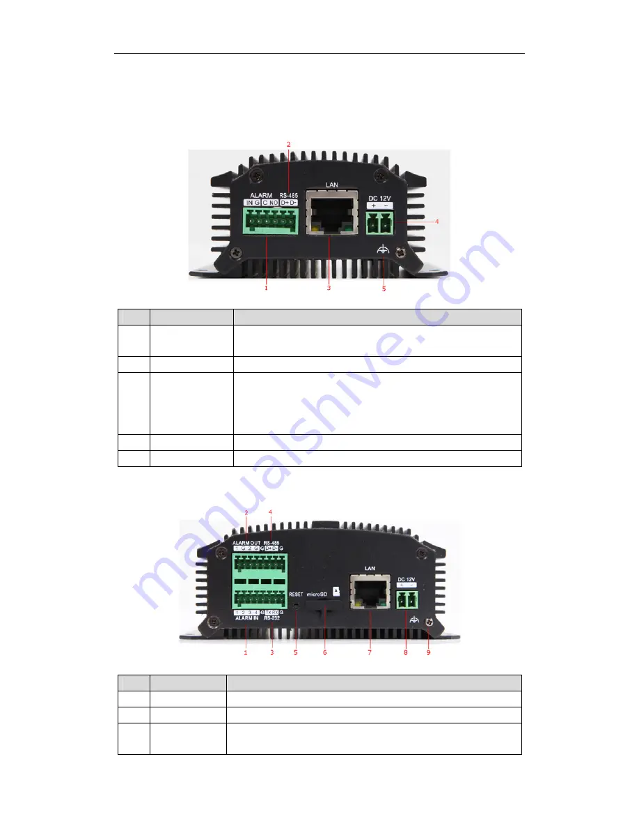
HER503-1:
Description of rear panel:
Item
Description
1
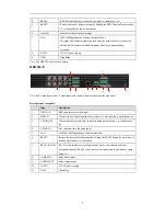
ALARM IN /OUT
Relay alarm input/output.
Note:
The alarm output terminal provides no JP2 pin.
2
RS-485
RS-485 serial interface; connect to pan/tilt unit, speed dome, etc.
3
LAN
10M/100Mbps adaptive Ethernet interface (PoE).
The right LED indicator lights in green when the network cable is connected,
and the left LED indicator blinks in orange when data is transmitting /
receiving.
4
DC12V
12V DC power supply.
5 GND
Grounding
Note:
The HER503-1 model provides no beeper.
HER503-4:
Description of rear panel:
Item
Description
1
ALARM IN
Relay alarm input.
2
ALARM OUT
Relay alarm output.
3
RS-232
Serial interface for configuration of device’s parameters or used as transparent
channel.


