Network
Dome
Camera
∙
Quick
Operation
Guide
14
bles
on
the
surface
of
the
ceiling.
Refer
to
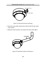
Conduit
Installation
on
the
Side
for
side
cable
routing.
eiling
by
aligning
the
holes
of
the
back
the
holes
on
the
ceiling.
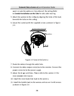
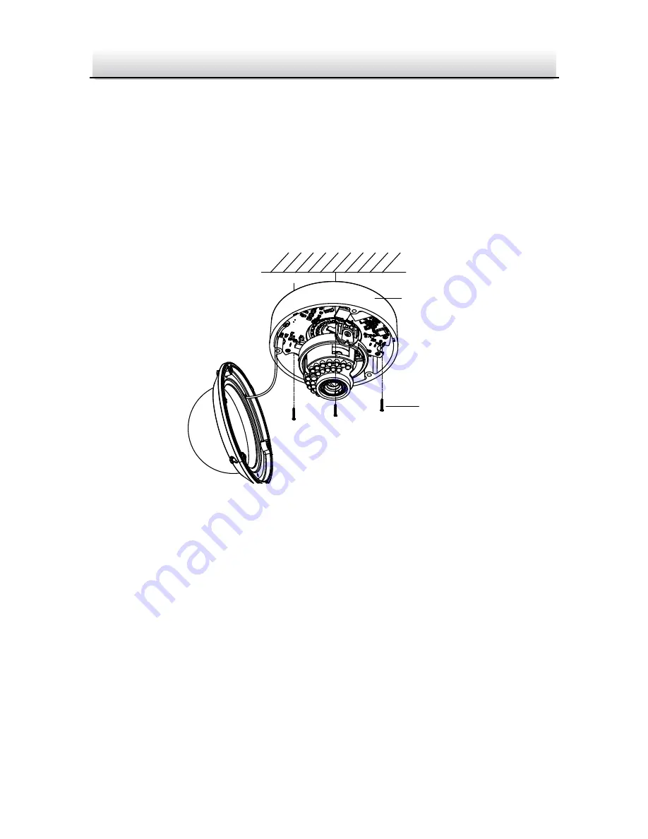
wn
in
Figure
Figure
2
‐
3
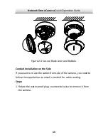
Secure
the
Camera
7.
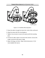
Route
the
cables
through
the
cable
hole.
8.
Connect
the
video
output
connector
to
the
monitor.
Connect
the
power
connector
to
the
power
supply.
9.
Ad
tion
2.3
for
more
detailed
information.
11.
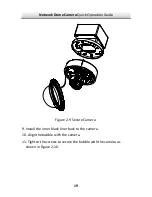
Install
the
bubble
back
to
the
camera
and
secure
it
with
screws
as
shown
in
Figure
2
‐
4.
want
to
route
the
ca
5.
Attach
the
camera
to
the
c
box
with
6.
Secure
the
camera
with
the
supplied
screws
as
sho
2
‐
3.
Screw
Back
Box
just
the
image
and
focus.
Please
refer
to
the
sec
10.
Install
the
inner
black
liner
back
to
the
camera.

