■
Installation
1. Dome Base Mounting
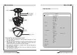
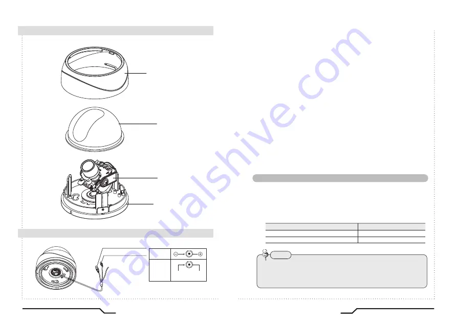
- Open the dome cover by loosening 3 screws using special wrench
provided.
- Mount the base of camera to a sturdy surface using 4 screws (1.5
inch) and 4 premade holes on the base of the dome.
2. Power Connect & Monitor Impedance
- DC12V/300mA regulated power supply (DC12V only)
AC24V Class 2 power supply (AC24V/DC12V)
- To avoid fire or shock hazard, must use a UL listed power supply.
- Set the monitor impedance switch to 75
Ω
. Check the impedance
switch when the screen turns blurred.
3. Camera Module Adjustment
- Loosen screws for 3-axis camera bracket and adjust the direction
and angle of camera.
- Make sure to retighten the screws for camera bracket.
- Set any function you wish to activate by using the OSD buttons.
4. Dome Cover Mounting
- Replace the dome cover to the base and tighten 3 screws.
■
Cable Connections
Control via RS-485 Interface
RS-485 Control Port
485 Control Board Connection Port
485+
(+) CONNECTION TERMINAL (TRX+)
(- ) CONNECTION TERMINAL (TRX-)
485-
The camera can be controlled by using external controllers like a Remote controller.
(RS-485 Communication)
• To control using a DVR or System Controller
Connect the RS-485 cable (TRX+, TRX-) to the connection port of the 485
control board that is connected to the DVR or System Controller.
• To control the camera by constructing an additional controller, use
Pelco-D protocol.
(Go Preset 95 : Enters into OSD menu or Set key function)
Note
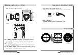
DOME COVER
GIMBAL A'SSY
BASE HOUSING
DECORATION RING
DC only
AC24V
DC12V
AC IN
DC IN
AC IN
DC IN
VIDEO
POWER
RS-485
13
WDR True Day&Night Dome Camera
12
WDR True Day&Night Dome Camera
Summary of Contents for HTC-16GWD28D
Page 18: ...MEMO...

