HTP-T800 User Manual
-14-
3. System Operation
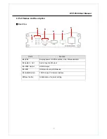
1. LED Display
Description of LEDs
System status can be monitored with LEDs.
LED
State
Description
Off No
power
PWR
Red Power
on
Green blinking
Normally operating
Red
System failure: Needs diagnostics
Constant change of colors
between Red and Green
NTSC/PAL setting does not match with input
video signal
Red Blinking
Failed to obtain IP address in DHCP mode
Constant change of colors
between Green blinking 2
times and Red blinking
once
Failed to register on DDNS server
Green blinking, Red blinks
once every 5 seconds
Video loss in Encoder system
STATUS
Orange blinking
Improper resolution setting in duplex mode
Off
No connection to remote system
Green
Connected to a remote system
Red blinking
Decoder only: trying to connect to an Encoder
LINK
Orange
Illegal connection (unsupported combination of
system modes)
Green
Data transmission in progress
Red Data
loss
DATA
Off No
data
transmission
2. Remote Video Monitoring
There are two ways to view the remote video when the connections are completed between a site and
center system. In order for a proper operation, an IP address must be set accordingly. Please refer to
True Manager
or
Remote Setting in Chapter 4 and 5
for further details.
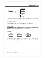
Video Monitoring with Decoder System
Once the encoder IP address is set in the remote IP address section of the decoder, the decoder
system will connect to the encoder system and start receiving the video images. Normally, a monitor
connected to the decoder will display video images.
Summary of Contents for HTP-T800
Page 1: ...HTP T800 H 264 VIDEO SERVER User Manual Ver 1 0...
Page 18: ...HTP T800 User Manual 17 Http port 80...
Page 22: ...HTP T800 User Manual 21 2 2 Video Configuration...
Page 27: ...HTP T800 User Manual 26 2 4 Network Configuration...
Page 30: ...HTP T800 User Manual 29 2 5 Serial Port Configuration...
Page 32: ...HTP T800 User Manual 31...
Page 33: ...HTP T800 User Manual 32 2 6 Event Configuration...


