Hunter 36 • Sails and Rigging
12.2
Sails & Rigging
Most sailors believe that sailing is hard work: all those lines
to tend, halyards to yank and sails to lug. Hunter Marine
has dispelled that myth once and for all! Innovations by
the crew at Hunter Marine have made sailing easier, safer
and more comfortable. The result - much more sailing fun!
Whether you are ready to set sail for the islands or just
around the buoys, your Hunter can really make a differ-
ence. Starting with the tall, fractional rig, which is a direct
descendent of the B&R rig, Hunter has engineered the
mast to carry less weight aloft with a smaller sections.
This is accomplished by utilizing swept-back spreaders
and reverse diagonals as well as mast support struts.
This combination provides superior strength without a
backstay and increases the stability at the same time.
By using a large roach main as the power sail, Hunter
has eased the effort in sail handling and allowed for real
versatility for all wind and sea conditions.
Your benefit: better performance with less effort. The
deck layout reflects the innovation that accompanies the
rig. An integrated arch protects the cockpit from snapping
main sheets and blistering sun with the optional bimini.
This arch keeps the cockpit clear and open.
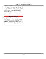
WARNING
!
!
Refer to Boating Safety, and the Getting Underway
chapters for safe boat handling information.
If this is your first boat of this type or you are changing
to a new boat you are not familiar with, please ensure
that you obtain handling and operating experience before
assuming command of the boat. This document is not a
course on boating safety or seamanship. Your dealer or
national sailing federation or yacht club will be pleased
to advise you of local sea schools, or competent instruc-
tors.
Never underestimate the potentially dangerous power of
wind, tide and the sea. Always ensure there is sufficient
trained and proficient crew on board to handle the boat
and its operating systems even in adverse conditions.
NOTE: Standing rigging will stretch slightly when initially
loaded. Therefore, the rigging may have to be further tensioned
slightly after a few sails in a strong breeze to compensate for
this initial stretch. Once the mast is tuned and initial stretch is
taken out, the rig should need retuning only at the beginning of
each season.
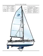
12.1 Main Rig Components
Anodized B&R Rig Mast
Boom
Dual Single Line Reefing System
Furling Jib
Inboard Jib Track w / Adjustable Cars
Internal Halyards led to Cockpit
Jib Furling System
Large Roach Mainsail w/Flaking System
Mainsheet on Arch
Self-Tailing Jib Winches w/Handles
Self-Tailing Rigging Winches w/Handles
Line Stoppers & Organizers
Over the course of the next few pages we will outline
some of the components featured here, along with some
of the optional components of your sails and rigging
aboard your Hunter sailboat.
12.2 The Mast
Your main and most vital rig component is the mast. It
carries the sails and is supported by the standing rigging
as shown on page 12.11.
Your Hunter features the B&R rig; a design by Lars
Bergstrom and Sven Ridder. The design was born in the
70’s and has been used on ocean racers as well as world
cruisers producing tremendous success. The B&R rig is
designed to eliminate inner forestays, backstays, and
running backstays. The 30-degree sweptback spreaders
and reverse diagonals support the mast sideways, fore,
and aft and the shrouds are discontinuous. Weight is
minimized and using a smaller mast section maximizes
airflow to the main. The angles between the shrouds and
forestay equal an even 120-degree triangle that evenly
spreads the load of the mast.
12.3 The Boom
The boom carries the lower sheeting point of your main
sail and is controlled by the main sheet, the vang and
the optional traveler lines. Page 12.12 contains illustra-
tions demonstrating the boom with reefing layout and the
Mainsheet Purchase layout.
•
•
•
•
•
•
•
•
•
•
•
•
Summary of Contents for H36
Page 1: ...Operator s Operator s Manual Manual H36 H36 V1 040107 P N 1031378 ...
Page 2: ......
Page 9: ...Introduction Introduction H36 H36 Chapter 1 Chapter 1 V1 040107 P N 1031378 ...
Page 14: ...Hunter 36 Introduction 1 6 Notes ...
Page 15: ...V1 040107 P N 1031378 and Documents Documents Forms Forms H36 H36 Chapter 2 Chapter 2 ...
Page 26: ...Hunter 36 Documents and Forms Maintenance Log Date Maintenance Performed Hourmeter 2 12 ...
Page 27: ...Hunter 36 Documents and Forms 2 13 Date Maintenance Performed Hourmeter Maintenance Log ...
Page 33: ...Hunter 36 Documents and Forms 2 19 Spare Parts List ...
Page 34: ...Hunter 36 Documents and Forms Dates of practice drills and onboard safety inspections 2 20 ...
Page 35: ...Hunter 36 Documents and Forms 2 21 My personal preferences for maintenance items safety gear ...
Page 36: ...Hunter 36 Documents and Forms Notes 2 22 ...
Page 37: ...DC 071609 Limited Limited Warranty Warranty Chapter 3 Chapter 3 ...
Page 38: ...This Page Intentionally Left Blank Hunter Limited Warranty 3 2 ...
Page 47: ...Boating Boating Safety Safety H36 H36 Chapter 4 Chapter 4 V1 040107 P N 1031378 ...
Page 68: ...Hunter 36 Boating Safety 4 22 Notes ...
Page 69: ...Chapter 5 Chapter 5 Fuel Fuel Systems Systems H36 H36 V1 040107 P N 1031378 ...
Page 75: ...Fig 5 7 A Quick Fuel Filter Reference Hunter 36 Fuel Systems 5 7 ...
Page 82: ...Notes Hunter 36 Fuel Systems 5 14 ...
Page 83: ...Underwater Underwater Gear Gear H36 H36 Chapter 6 Chapter 6 V1 040107 P N 1031378 ...
Page 92: ...Hunter 36 Underwater Gear 6 10 Notes ...
Page 93: ...DC Electric DC Electric Systems Systems H36 H36 Chapter 7 Chapter 7 V1 040107 P N 1031378 ...
Page 103: ...Hunter 36 DC Electric 7 11 7 8 BASIC DC POWER SUPPLY SYSTEM DIAGRAM ...
Page 104: ...Hunter 36 DC Electric 7 12 Notes ...
Page 106: ...Hunter 36 DC Electric 7 14 Notes ...
Page 108: ...Hunter 36 DC Electric 7 16 Notes ...
Page 109: ...AC Electric AC Electric Systems Systems H36 H36 Chapter 8 Chapter 8 V1 040107 P N 1031378 ...
Page 118: ...This Page Intentionally Left Blank Hunter 36 AC Electric Systems 8 10 ...
Page 119: ...Hunter 36 AC Electric Systems 8 11 7 8 AC DC Electric Power Supply Diagram pp y g ...
Page 120: ...Hunter 36 AC Electric Systems 8 12 This Page Intentionally Left Blank ...
Page 121: ...Hunter 36 AC Electric Systems 8 13 Notes ...
Page 122: ...Hunter 36 AC Electric Systems 8 14 Notes ...
Page 123: ...Water Water Systems Systems H36 H36 Chapter 9 Chapter 9 V1 040107 P N 1031378 ...
Page 130: ...Hunter 36 Water Systems 9 8 This Page Intentionally Left Blank ...
Page 132: ...Hunter 36 Water Systems 9 10 This Page Intentionally Left Blank ...
Page 133: ...Hunter 36 Water Systems 9 11 Notes ...
Page 134: ...Hunter 36 Water Systems 9 12 Notes ...
Page 135: ...Waste Waste Systems Systems H36 H36 Chapter 10 Chapter 10 V1 040107 P N 1031378 ...
Page 144: ...This Page Intentionally Left Blank Hunter 36 Waste and Sanitation Systems 10 10 ...
Page 146: ...This Page Intentionally Left Blank Hunter 36 Waste and Sanitation Systems 10 12 ...
Page 148: ...This Page Intentionally Left Blank Hunter 36 Waste and Sanitation Systems 10 14 ...
Page 149: ...Sump Pump Layout Grey Water p p y y Hunter 36 Waste and Sanitation Systems 10 15 ...
Page 150: ...This Page Intentionally Left Blank Hunter 36 Waste and Sanitation Systems 10 16 ...
Page 152: ...This Page Intentionally Left Blank Hunter 36 Waste and Sanitation Systems 10 18 ...
Page 153: ...Hunter 36 Waste and Sanitation Systems 10 19 Notes ...
Page 154: ...Hunter 36 Waste and Sanitation Systems 10 20 Notes ...
Page 164: ...Hunter 36 Engines and Transmissions 11 10 This Page Intentional Left Blank ...
Page 165: ...V1 040107 P N 1031378 Sails Sails Rigging H36 H36 Chapter 12 Chapter 12 and and ...
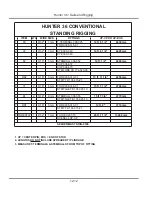
Page 171: ...Hunter 36 Sails and Rigging 12 7 Standing Rigging Details Standard ...
Page 172: ...Hunter 36 Sails and Rigging 12 8 Standing Rigging Details Furling ...
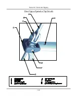
Page 173: ...Hunter 36 Sails and Rigging 12 9 Mast Upper Spreader Tip Details pp p p H A B C D E F G ...
Page 174: ...Hunter 36 Sails and Rigging 12 10 C A B D E F G H J K I Mast Lower Spreader Tip Details p p ...
Page 175: ...Hunter 36 Sails and Rigging 12 11 Standing Rigging Details ...
Page 179: ...Hunter 36 Sails and Rigging 12 15 Typical Boom Reefing Layout yp g y ...
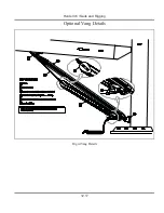
Page 180: ...Hunter 36 Sails and Rigging 12 16 Rope Vang Details Standard Vang Details ...
Page 181: ...Hunter 36 Sails and Rigging 12 17 Rigid Vang Details Optional Vang Details ...
Page 184: ...Hunter 36 Sails and Rigging 12 20 JIB LINE TIES OFF ON CLEAT Jib Furling Line Layout ...
Page 185: ...Hunter 36 Sails and Rigging 12 21 Bridle Configuration ...
Page 186: ...Hunter 36 Sails and Rigging 12 22 Optional Mainsheet Traveler Layout ...
Page 190: ...Hunter 36 Sails and Rigging 12 26 Optional Spinnaker Layout ...
Page 191: ...Hunter 36 Sails and Rigging 12 27 Notes ...
Page 192: ...Hunter 36 Sails and Rigging 12 28 Notes ...
Page 193: ...Getting Getting Underway Underway H36 H36 Chapter 13 Chapter 13 V1 030107 P N 1031378 ...
Page 200: ...Hunter 36 Getting Underway 13 8 Notes ...
Page 201: ...Maintenance H36 H36 Chapter 14 Chapter 14 V1 040107 P N 1031378 ...
Page 214: ...Notes Hunter 36 Maintenance 14 14 ...
Page 215: ...Exterior Lifting Points g Hunter 36 Maintenance 14 15 ...
Page 216: ...Hunter 36 Maintenance 14 16 This Page Intentionally Left Blank ...
Page 217: ...Hunter 36 Maintenance 14 17 Exterior Lifting Points Saildrive g ...
Page 218: ...Hunter 36 Maintenance 14 18 This Page Intentionally Left Blank ...
Page 219: ...Glossary Glossary H36 H36 Chapter 15 Chapter 15 V1 040107 P N 1031378 ...

