background image

30 


4.


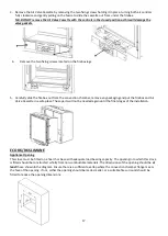
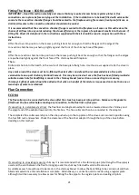
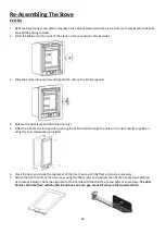
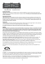
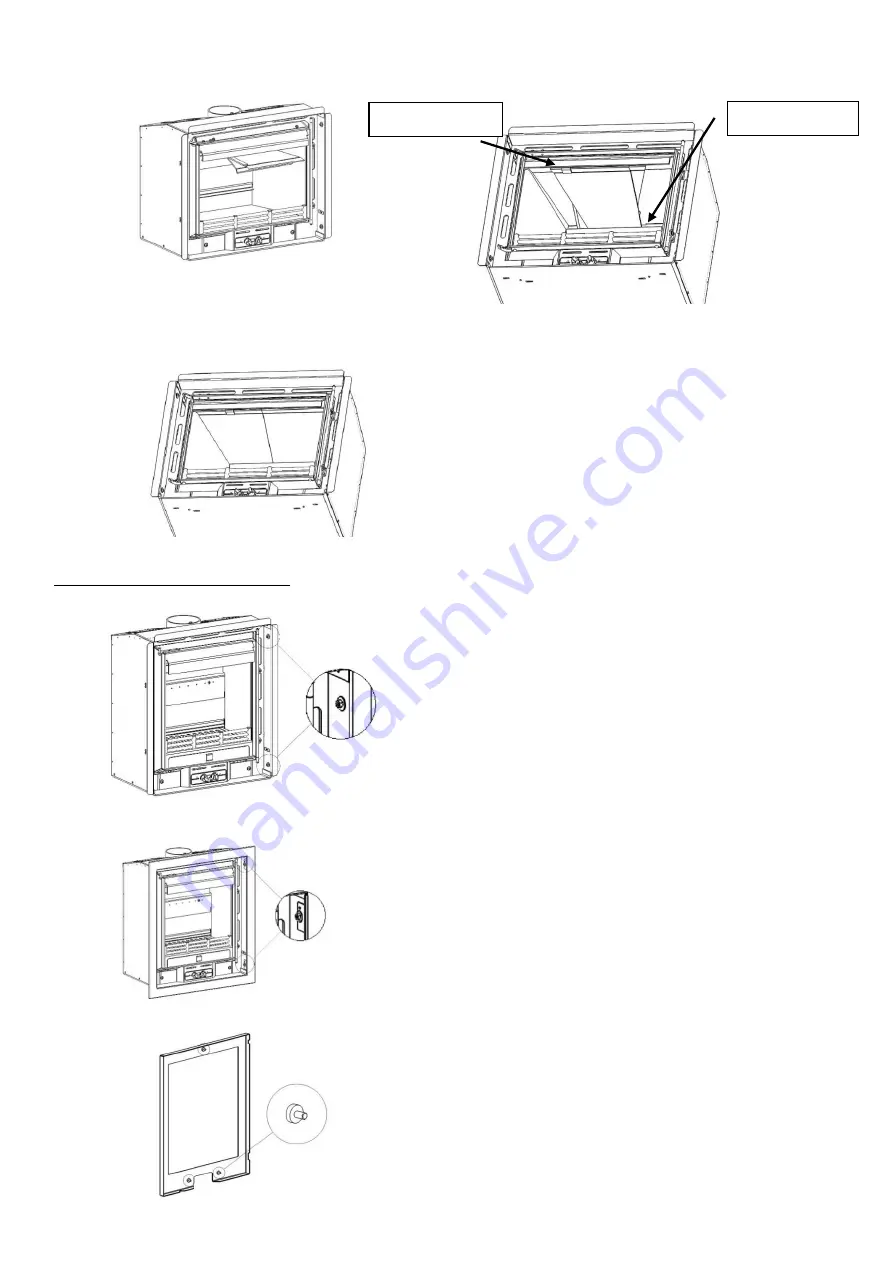
Lift the two baffles up together inside the firebox to the right-hand side of the baffle support bracket, slide the 
baffles to the left and rest them on the support bracket at the front of the stove and Tertiary Air Bar. 


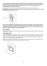
5.


Slide the Left-hand baffle to the left and the right-hand baffle to the right, push them towards the rear of the 
firebox so that the baffles drop down and sit tightly together as shown. 


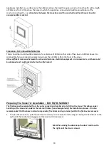
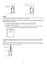
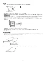
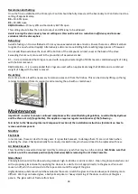
Fitting The Frame Pack (all) 

1.


Loosen the four M6 Nuts to the ends of the studs on the convection chamber sides.  


2.


Slide the frame into position, making sure that the lower inner edge of the frame is in line with the base of the 
stove, and tighten the nuts with a 10mm spanner. 


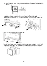
3.


Place a round spacer (supplied with the frame pack) over each of the fascia studs. 


Tertiary Air Bar 

Support Bracket 

Summary of Contents for Di Lusso Series

Page 1: ...1 Eco R4 Inset Eco R5 Inset Eco R6 Inset Eco R6 Slimline Inset Wood Burning Inset Stove Instructions for Installation Operating Maintenance Servicing Instructions JINEDLUIN REV B 27 03 2019 ...

Page 2: ...R5 INSET FOUR SIDED FRAME ECO R5 INSET THREE SIDED FRAME STOVE EDDLR05 STOVE EDDLR05 FRAME DLR5FP4B50 BLACK FRAME DLR5FP3B50 BLACK FRAME DLR5FP4P50 PEWTER FRAME DLR5FP3P50 PEWTER ECO R6 R6 SLIMLINE INSET FOUR SIDED FRAME ECO R6 R6 SLIMLINE INSET THREE SIDED FRAME STOVE EDDLR06 EDDLR06S STOVE EDDLR06 EDDLR06S FRAME DLR6FP4B50 BLACK FRAME DLR6FP3B50 BLACK FRAME DRL6FP4P50 PEWTER FRAME DLR6FP3P50 PEW...

Page 3: ...6 SLIMLINE ENCLOSURE INSTALLATION 26 27 RE ASSEMBLING THE STOVE 31 OPERATING INSTRUCTIONS 31 34 MAINTENANCE 34 35 TROUBLESHOOTING 36 37 SPARES 38 42 INSTALLATION AND COMMISSIONING CHECK LIST 43 SERVICE RECORDS 44 FULL WARRANTY INFORMATION 45 46 Welcome to the Hunter Stoves family and thank you for purchasing an Eco Di Lusso Inset stove This stove was designed and built to be a high performance hea...

Page 4: ...mm 127mm 127mm VENTILATION Where leakage is greater than 5m hour m Ventilation normally required 550mm per kW output over 5kW NONE 660mm 715mm Where leakage is less than or equal to 5m hour m Ventilation normally required 550mm per kW output 2695mm 3410mm 3465mm Minimum Clearance to Combustible Material At the sides of the stove 250mm from outside of frame 450mm from outside of frame 400mm from ou...

Page 5: ...ecided at the discretion of a qualified installer and a flue draught interference test must be performed Do not obstruct the ventilation required for the safe use of this appliance Competent Persons Scheme Members of the following schemes may self certify the installation of this stove If the installer is not a member of one of these schemes your local Building Control Department must approve the ...

Page 6: ...y or the infirm The fireguard should be manufactured in accordance with BS8423 Fireguards for use with solid fuel appliances Do Not Over Fire It is possible to fire the stove beyond its design capacity This could damage the stove so watch for signs of over firing If any part of the stove starts to glow red the stove is in an over fire situation and the controls should be adjusted accordingly Never...

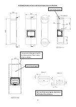
Page 7: ... furniture away Ensure the Fire Brigade can gain access to your roof space in order to check for fire spread Installation N B All dimensions are in Millimetres Appliance Dimensions ECO R4 Flue Outlet Position The flue outlet angle and position are determined by the orientation of the flue collar The outlet can be either vertical or leant backwards by 30 To change the angle rotate the flue collar b...

Page 8: ... position are determined by the orientation of the flue collar The outlet can be either vertical or leant backwards by 30 To change the angle rotate the flue collar by 180 The effective centre dimensions in millimetres are shown below ECO R6 ECO R6 SLIMLINE ...

Page 9: ...ions and Building Regulations The chimney flue should have a vertical height of at least 4 5 metres and should terminate in accordance with Table 2 If the chimney is believed to have previously served an open fire installation it is possible that the higher flue gas temperature from the stove may loosen deposits that were previously firmly adhered with the consequent risk of flue blockage It is th...

Page 10: ...his appliance will fit into a standard 16 fireplace opening if the clay fire back is removed Any non combustible walls within 50mm of this appliance should be at least 200mm thick and should extend at least 300mm above the top of the appliance and at least 1 2 metres above the hearth Any walls more than 50mm from the appliance may be reduced to a thickness of 75mm Ensure the inter connecting flue ...

Page 11: ...not suitable for solid fuel Direct Air Adaptor If fitting the direct air adaptor kit the opening depth may need to be increased Read the instructions supplied with the kit before proceeding Hearth Requirements A constructional hearth with a minimum thickness of 225mm should be provided The constructional hearth should be made of solid non combustible material and can include any solid non combusti...

Page 12: ...r than 800mm from the front of the stove Allow sufficient clearance between the stove and pictures electrical equipment or ornaments etc as these could be damaged and could potentially create a fire hazard Removing Internal Components All All internal components must be removed prior to fitting the stove This will make handling the stove easier allow access to fixings and the flue outlet as well a...

Page 13: ...ide both baffle plates to the centre with left hand baffle on top of right hand baffle and lift out of stove together 4 Remove the two side bricks by lifting them up to release them from the slots in the base brick Swing the bricks into the centre and remove them from the stove 5 Remove the three rear brick sections Eco R4 and two rear bricks Eco R5 Eco R6 noting their positions and orientation 6 ...

Page 14: ...onvection Duct Kit the dimensions of the opening may need to be altered Read the instructions supplied with the kit before proceeding Installation Into A Solid Non Combustible Wall This stove must be fitted on a hearth or base with adequate load bearing capacity The opening into which this stove is fitted should be constructed wholly from non combustible materials The dimensions of the opening sho...

Page 15: ...earth must be clearly marked This can be done by adding a super imposed hearth on top of the constructional hearth e g a slate slab on top of a solid concrete floor Appliances installed with the base plate lower than 300mm above the hearth should have a constructional hearth extending to at least 650mm in front of the stove and 150mm at the sides Appliances installed with their base plate 300mm or...

Page 16: ...convection chamber prior to fitting the stove This allows easier handling of the stove and protects the internal firebox from damage during the installation process It is also recommended that the loose internal components Ash pan grate fire bricks baffle and log retainer within the firebox are removed 1 To open the stove door pull the door handle towards you to release it from the Magnet Swing th...

Page 17: ...ging and put the firebox and Air Valve Cassette in a safe place These parts will not be needed again until the final stages of the installation ECO R6 R6 SLIMLINE Appliance Opening This stove must be fitted on a hearth or base with adequate load bearing capacity The opening into which this stove is fitted should be constructed wholly from non combustible materials The dimensions of the opening sho...

Page 18: ...ugh incorrect use or installation Fire surround back panels suitable for solid fuel are usually in three sections and slabbed Many fire surrounds are suitable only for use with gas and electric fires and therefore not suitable for solid fuel Direct Air Adaptor If fitting the direct air adaptor kit the opening depth may need to be increased Read the instructions supplied with the kit before proceed...

Page 19: ...t clearance between the stove and pictures electrical equipment or ornaments etc as these could be damaged and could potentially create a fire hazard Preparing The Stove For Installation ECO R6 R6 SLIMLINE The firebox must be separated from the outer convection chamber prior to fitting the stove This allows easier handling of the stove and protects the internal firebox from damage during the insta...

Page 20: ...ng on the fascia to slide the cassette out from under the firebox N B DO NOT remove the Air Valve Cassette with the controls in the closed position as this will damage the valve gaskets 4 Remove the two fixing screws located on the firebox legs 5 Carefully slide the firebox out from the convection chamber remove any packaging and put the firebox and Air Valve Cassette in a safe place These parts w...

Page 21: ...x parts vermiculite to one part Ordinary Portland Cement This may be carried out once the flue has been fitted provided a suitable access hole for backfilling is made in the chimney breast see section on connecting to a masonry chimney Sufficient water should be added so that when a handful of the mixture is squeezed no more than one or two drops of water are released Flue Connection ECO R4 The fl...

Page 22: ... the flue collar gasket in position 4 Offer the flue collar into position from inside the convection chamber and fix in place using the four M8 countersunk screws Ensure that the screw heads are not proud of the flue collar flange If connecting to a stainless steel liner the flue liner and single skin adaptor can be lowered down the chimney and the spigot end of the adaptor lowered into the convec...

Page 23: ... be read in conjunction with these instructions 1 Offer the convection chamber into position in the recess pushing it back far enough so that the flanges on the edges are pushed up tightly against the front face of the chimney breast fireplace 2 Drill a 6mm hole into the hearth in the centre of the base plate fixing hole Use the screw supplied to fix the stove in place Any voids around the stove m...

Page 24: ...he ECO R5 R6 R6 Slimline have been designed tested and approved to be installed either into solid non combustible material or into an enclosure according to the following specification It is the duty of the installer to ensure that the requirements of this specification and all relevant standards are met There must be no combustible material within the construction of the enclosure The stove shoul...

Page 25: ...ide distance is for material proud of the front face of the wall The enclosure should be stood wholly above a non combustible hearth with a minimum thickness of 12mm The hearth should extend at least 225mm in front of the stove and 150mm either side The hearth may be super imposed ...

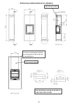
Page 26: ...ls all dimensions in millimetres Internal heat shield All panels including heat shield to be produced from 30mm Skamol Super Isol Board Internal heat shield N B Ventilation openings are identical on both sides of the enclosure ...

Page 27: ... Details all dimensions in millimetres Internal heat shield All panels including heat shield to be produced from 30mm Skamol Super Isol Board Internal heat shield N B Ventilation openings are identical on both sides of the enclosure ...

Page 28: ...door ajar 5 Offer the Door Fascia into position passing the 3x M6 studs through the holes in the door and fix in position using the nuts and washers provided 6 Close the door and check the alignment of the Door Fascia with the frame Adjust as necessary 7 Attach the door handle to the door lever using the M6 screws and washers then fit the handle fascia plate as per drawing below Check the alignmen...

Page 29: ...Wipe off any excess fire cement around the inside of the flue which may have been squeezed out when fitting the firebox 6 Refit the fire bricks grate support ash pan log retainer and baffle 7 Check that the valves are in the fully open position fully clockwise and refit the Air Valve Cassette 8 Close the stove door ECO R6 SLIMLINE 1 Refit the three fixing screws and secondary baffle plate through ...

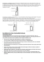
Page 30: ... right push them towards the rear of the firebox so that the baffles drop down and sit tightly together as shown Fitting The Frame Pack all 1 Loosen the four M6 Nuts to the ends of the studs on the convection chamber sides 2 Slide the frame into position making sure that the lower inner edge of the frame is in line with the base of the stove and tighten the nuts with a 10mm spanner 3 Place a round...

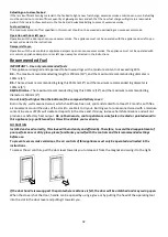
Page 31: ... open the door and operate the air controls THE CLEAN AIR ACT 1993 AND SMOKE CONTROL AREAS Under the Clean Air Act local authorities may declare the whole or part of the district of the authority to be a smoke control area It is an offence to emit smoke from a chimney of a building from a furnace or from any fixed boiler if located in a designated smoke control area It is also an offence to acquir...

Page 32: ...100mm 4 R6 R6 Slimline The maximum recommended log length is 330mm 14 and the maximum recommended log diameter is 100mm 4 Do not load fuel higher than the bottom of the compound tertiary cover Burn only dry well seasoned wood which should have been cut split and stacked for at least 12 months with free air movement around the sides of the stack to enable it to dry out Burning wet or unseasoned woo...

Page 33: ... established before placing several pieces of small dry kindling in a crisscross fashion above the firelighters taking care not to smother the fire Close the stove door Once the kindling is well alight open the door and build the fire by gradually adding slightly larger pieces of wood closing the door afterwards Once the fire is established close the Primary Air Control anti clockwise and add more...

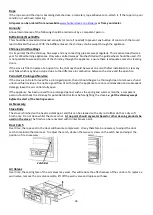
Page 34: ...og retainer to release it from its supports and removing the ash with a small shovel Maintenance Important In order to ensure continued compliance with current Building Regulations Local Authority Byelaws and the Clean Air Act if applicable this appliance requires regular maintenance of the following N B Refer to the Removing Internal Components section of the installation instructions for details...

Page 35: ...n fire Periods Of Prolonged Non Use If the stove is to be left unused for a prolonged period then it should be given a thorough clean to remove ash and unburned fuel residues To enable a good flow of air through the appliance to reduce condensation and subsequent damage leave the air controls fully open If the appliance has been unused for a prolonged period such as the spring and summer months a ...

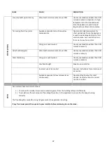
Page 36: ...ve smoke spillage into room when appliance door is opened Low flue draught Speak to your installer Incorrect additional ventilation air in to the building Speak to your installer Continuous smoke spillage into the room when stove is in use Blocked flue Open all doors and windows to ventilate the room Allow the fire to go out Check flue for blockage Do not re use until the problem has been identifi...

Page 37: ...moisture content over 20 Use dry seasoned wood less than 20 moisture content Glass blackening Using poor quality wood Use dry seasoned wood less than 20 moisture content Low flue draught Speak to your installer Incorrect use of air control See user instructions for correct use of air control Appliance operated at low temperatures continuously Operate at high output for short periods See instructio...

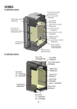
Page 38: ...38 SPARES ECO R4 BODY SPARES ECO R5 BODY SPARES ...

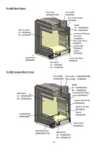
Page 39: ...39 ECO R6 BODY SPARE ECO R6 SLIMLINE BODY SPARE ...

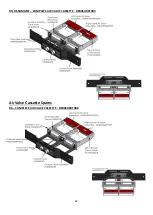
Page 40: ...40 DOOR SPARES ECO R4 COMPLETE DOOR CODE HMR04ARRT027 ECO R5 COMPLETE DOOR CODE HMR05ARRT005 Complete Rope Seal Kit SCPDL5RSK Stove Spares AIR VALVE CASSETTE SPARES ...

Page 41: ...41 ECO R6 R6 SLIMLINE COMPLETE DOOR CODE HMR06ARRT005 Door Handle Fascia Air Valve Cassette Spares R4 COMPLETE AIR VALVE CASSETTE HMR04ARRT004 Complete Rope Seal Kit SCPDL6RSK ...

Page 42: ...42 R5 R6 SLIMLINE COMPLETE AIR VALVE CASSETTE DER05ARRT009 Air Valve Cassette Spares R6 COMPLETE AIR VALVE CASSETTE DER06ARRT008 ...

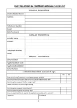
Page 43: ...43 ...

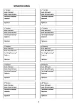
Page 44: ...44 ...

Page 45: ...tion date for the second year of the standard warranty to be valid and within every 12 month anniversary thereafter to maintain the validity and coverage of any extended warranty For this purpose the installation and user instructions supplied with the appliance makes a provision for receipts and annual services to be recorded This is needed in the event of a claim during the warranty period 4 Onl...
Page 46: ...es Group products is not covered under the warranty 6 Consequential loss relating to decorations soft furnishings or other household assets is not covered under the warranty 7 Cost associated with the removal and re installation of an appliance subject to a warranty claim Hunter Stoves Group total liability will only extend to the total purchase price paid for the goods in any warranty claim Hunte...
Reviews: