7
JINTDI05 Rev E 20/04/54
I
NSTRUCTIONS FOR FITTING THE
OPTIONAL
D
IRECT
A
IR
K
IT
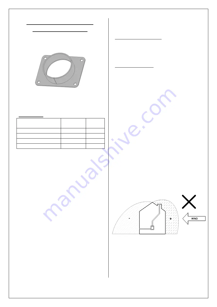
An optional Direct Air Adaptor (Part No: HCN05079)
is supplied with this appliance.
If the Direct Air Adaptor is to be fitted a Direct Air
kit will need to be purchased.
Direct Air Kit Code: (HCE16ARRT007)
Contents of kit
Description
Part
Number
Quantity
Adaptor Coupling
DACM80
1
Aluminium Duct
DAPM80
1
Bull Nose Vent & Flange
DAVM80
1
Duct Clip
FHC1060135
1
These instructions cover the installation of the
Direct Air Adaptor kit to the Hunter Inset 5 MKII
stoves.
This Direct Air Adaptor allows the combustion air
for the stove to be ducted directly from outside.
N.B. This does not constitute a “room sealed
installation” as some air is allowed to pass
through the stoves inlet duct.
This provides relief
from draught fluctuations and will help to clear the
air in the room should flue gas spillage occur.
It is important that your stove is correctly installed
as Hunter cannot accept responsibility for any fault
arising from incorrect use or installation.
The installation must comply with current Building
Regulations, national and European standards,
Local Authority Byelaws and other specifications or
regulations as they affect the installation of the
stove.
The Building Regulations requirements may also
be met by adopting the relevant recommendations
in the current issues of British Standards BS 8303
and BS EN 15287-1.
Competent Persons Scheme
Hunter recommend that this Direct Air Adaptor is
installed by a member of an accredited competent
persons scheme e.g. Hetas.
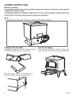
Siting of the Inlet Grille
Due consideration should be given to the siting of
the inlet grill to ensure that strong winds on either
the flue terminal, inlet grill or the building itself
will not cause the flow of flue gasses or
combustion air to be stalled or reversed.
If in doubt the inlet duct should be divided by a tee
piece and two inlet grills fitted on opposite sides of
the building. Alternatively the duct may be
connected to a space or chamber under the floor
on which the stove is installed which is ventilated
from all sides of the building.
Take note of prevailing winds in the area as well as
any tall buildings or trees that may be present and
could potentially create pressure zones around the
chimney terminal.
Do not fit the inlet vent on the downwind side of
the building unless the flue terminal is also on the
same side. Otherwise downdraft may occur in
windy conditions.
Care must also be taken when siting the inlet grille
to ensure that it will not become susceptible to
blockage.


