background image

JINTDI05 Rev E 20/04/54 

PRE-INSTALLATION REQUIREMENTS 

 
P

LEASE CHECK THE FOLLOWING

Any existing chimney/flue system must be 
confirmed as suitable for this appliance as defined 
in Building Regulations Document J.  
It must be swept and inspected, by a competent 
person (see notes), to confirm that is structurally 
sound and free from cracks and obstructions. 
The diameter of the Flue should not be less than 
Ø125mm and not more than Ø230mm. Do not 
connect to systems that have large voids or 
spaces. If any of these requirements are not met, 
the chimney should be lined by a suitable method. 
 
If the chimney is suspected of previously serving 
an open fire it must be swept again, within a 
month of regular use, to clear any soot that may 
have been dislodged due to the variation in 
combustion levels and higher flue gas 
temperature levels. 
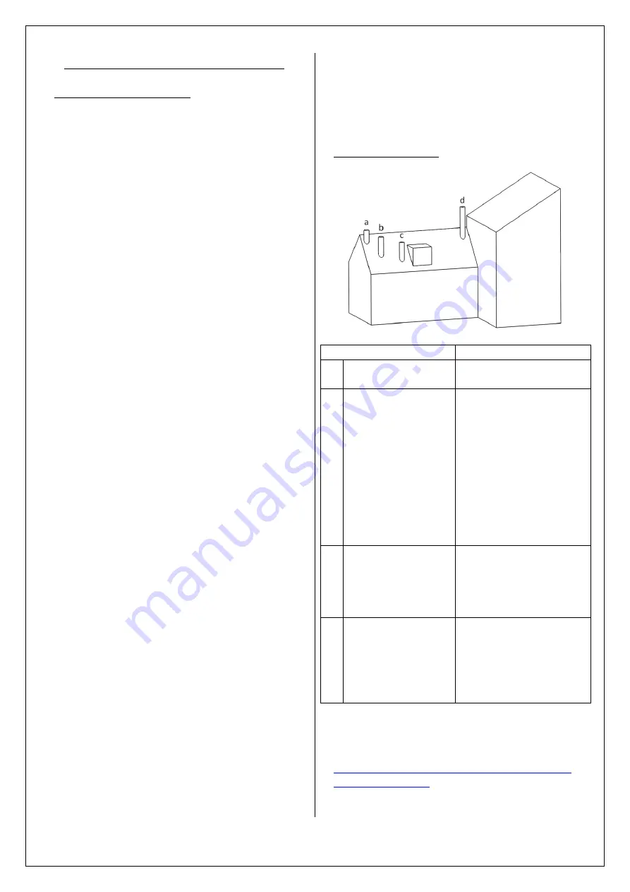
The chimney/flue system exit must comply with 
Building Regulations Document J 
The minimum height of the chimney/flue system 
must be 4.5 metres and should terminate in 
accordance with table 1. 
 
Make provision to access the chimney/flue system 
for cleaning and the removal of debris.  
If  there  is  no  existing  chimney  then  either  a 
prefabricated  block  chimney  in  accordance  with 
Building  Regulations  Approved  Document  J,  or  a 
twin-walled insulated stainless steel flue to BS4543 
can  be  used.    These  chimneys  must  be  fitted  in 
accordance  with  the  manufacturer’s  instructions 
and  Building  Regulations.  New  masonry  and  flue 
block  chimneys  must  meet  the  requirements  of 
Building  Regulations  Document  J.  Any  connecting 
flue  pipe  systems  must  also  meet  these 
regulations. 
Please check the suitability of the fireplace and/or 
surround for use with this appliance before 
installing it. Many Fire Surrounds are only suitable 
for use with gas and electric fires and therefore 
may not suitable for this Solid Fuel Appliance. 
Please check you Fire Surround. 
Fire  Surround  Back  Panels  suitable  for  solid  fuel 
are usually in three sections and slabbed.  
 

If you have any doubts about the suitability 
of your chimney, consult your local 
Dealer/Stockist

Both the chimney and flue pipe must be 
accessible for cleaning and if ANY part of the 
chimney cannot be reached through the 
stove (with baffle removed), a soot door 
must be fitted in a suitable position. 


F

LUE OUTLET 

P

OSITIONS


Position on Roof 

Clearances to flue exit 

At or within 
600mm of the ridge 

At least 600mm 
above the ridge 

Elsewhere on a roof 
(Pitched or Flat) 

At least 2.3 M 
horizontally from the 
nearest point on the 
weather surface and: 
a) At least 1.0 M above 
the highest point of 
intersection between the 
chimney and weather 
surface; or 
b)at least as high as the 
ridge 

Below (on a pitched 
roof) or within 2.3 M 
horizontally to an 
opening window or 
dormer 

At least 1.0 M above the 
top of the opening 

Within 2.3 M of an 
adjoining or 
adjacent building, 
whether or not 
beyond the 
boundary 

At least 600mm above 
any part of the adjacent 
building within 2.3 M 


Table1.

 – Flue Terminal Positions 

 
A full copy of Document J can be found here: 

http://www.planningportal.gov.uk/uploads/br/BR
_PDF_ADJ_2010.pdf


Summary of Contents for Telford Inset 5 MKII

Page 1: ...JINTDI05 Rev E 20 04 15 Telford Inset 5 MKII Models CVSTI05FM CVTI05FM Instructions for Installation Operation Maintenance Servicing ...

Page 2: ... components and the use of un authorised fuels Consumables are deemed to be Glass Seals Gaskets Grate Components Log Retainers Baffles and the surface finish of the appliance The Warranty will only be valid if the appliance is installed by an appropriately qualified engineer in accordance with the manufacturer s instructions and to the appropriate Building Regulations and or Local By Laws and serv...

Page 3: ... OUTPUT 4 9 KW CO Emission at 13 O2 0 19 Mean Flue Gas Temperature 292 C EFFICIENCY 77 1 Flue Gas Mass Flow 4 3 g s Minimum clearance to combustible material Top of Fire Surround 200mm Side of Fire Surround 150mm Side Wall 300mm This appliance is suitable for intermittent burning This appliance is not suitable for use in a shared flue Read and follow the operating instructions Use only recommended...

Page 4: ...ods must not be installed in the same space or room as this can cause the appliance to emit fumes into the room Do not obstruct the ventilation required for the safe use of this appliance COMPETENT PERSONS SCHEME Hunter Stoves recommend that this stove is installed by a member of an accredited competent persons scheme e g HETAS If the installer is not a member of a competent person s scheme it is ...

Page 5: ...mit fumes Occasional fumes from de ashing and refueling may occur Persistent fume emission must not be tolerated This appliance should not be operated with the door open If fume emission does persist then the following action should be taken immediately Open Doors and windows to ventilate room Let the fire out or eject and safely dispose of fuel from the appliance Check for flue chimney blockage a...

Page 6: ...rectly connected to the Inset 5 MKII Flue adaptor as this may result in deformation of the liner TO FIT THE FLUE ADAPTOR Remove all the stove interior parts and door s as detailed on page 12 Unscrew the two M8 screws from the inside of the stove and remove the Flue Infill plate Replace the Flue Infill Plate with the Flue Adaptor Apply fire cement to the mating surfaces of the adaptor and stove flu...

Page 7: ...or regulations as they affect the installation of the stove The Building Regulations requirements may also be met by adopting the relevant recommendations in the current issues of British Standards BS 8303 and BS EN 15287 1 Competent Persons Scheme Hunter recommend that this Direct Air Adaptor is installed by a member of an accredited competent persons scheme e g Hetas Siting of the Inlet Grille D...

Page 8: ...s and remove the Direct Air cover plate Replace the Direct Air Cover Plate with the Direct Air adaptor Screw the Direct Air adaptor in place with the four M6 screws and washers Measure the fireplace opening and check that there is sufficient room for the Direct Air Adaptor and that the position of any hole for the flexible ducting and any insulation is suitably sized and positioned Carry out any n...

Page 9: ...onry and flue block chimneys must meet the requirements of Building Regulations Document J Any connecting flue pipe systems must also meet these regulations Please check the suitability of the fireplace and or surround for use with this appliance before installing it Many Fire Surrounds are only suitable for use with gas and electric fires and therefore may not suitable for this Solid Fuel Applian...

Page 10: ...ce the publication of these instructions COMPETENT PERSONS SCHEME Members of the following schemes may self certify the installation of this stove If the installer is not a member of one of these schemes your local Building Control Department must approve the installation Scheme Web address Telephone APHC Association of Plumbing and Heating Contractors Certification Limited www aphc co uk 0121 711...

Page 11: ...ble materials A hearth with a minimum thickness of 125mm should be provided The hearth should extend to at least 300mm in front of the stove and 150mm at the sides and should be in accordance with the current building regulations In all instances the hearth and fireplace recess should be made of non combustible material The appliance shall be installed on a floor with adequate load bearing capacit...

Page 12: ...t will clear the opening and remove 4 Remove the grate bars by lifting them away from the cam bar and pulling forward out of the rear grate support The singular bars should be removed first noting their positions low or high leaving the two static triangular bars in place 5 Pull the Baffle forward and to the left hand side allowing the right hand edge of the Baffle to drop down into the stove and ...

Page 13: ...hem away from the cam bar and pulling forward out of the rear support N B When re installing the side bars need to be installed first followed by the singular bars The final two grate bars should be installed at the same time for ease of fit 13 Remove the cam bar by firstly sliding it to the right until the left hand end is clear of the hole 14 Then maneuver the left end of the cam bar into the vo...

Page 14: ...ope seal is compressed forming a tight seal between the stove and fireplace 4 Drill into the existing fireback through the fixing holes in the body see below using a 6mm drill bit 5 Place the screws provided into the fixing holes and gently tighten until the stove feels secure 6 Fill the fixing holes with fire cement to form an airtight seal 7 Seal the area where the throat meets the flue outlet o...

Page 15: ... appliance to heat up slowly ensuring that no products of combustion enter into the room When the appliance has reached working temperature open the Door and carry out a spillage test using a smoke match around the door opening If there is excessive spillage please allow the appliance to cool and then re check the chimney flue system and ventilation Do not run the stove at full output for at least...

Page 16: ...ows open AEROSOLS Do not use an aerosol spray on or near the stove when it is alight AIR CONTROLS This stove has been designed to burn cleaner and more efficiently than a conventional stove If used correctly this stove will burn far more efficiently than normal with the obvious notable feature of CLEAN GLASS For this product to work properly it must be used correctly It is essential that the stove...

Page 17: ...derside of the grate REDUCED COMBUSTION In order to reduce the combustion of the fire to a minimum close the primary air controls then close the secondary air slider by moving the handle all the way to the left If the controls are left in this position the fire will receive the minimum of air and will die down If you want to revive the fire it is recommended that the Primary Air control is open fi...

Page 18: ... appliances for use in smoke control areas in England In Scotland and Wales this power rests with Ministers in the devolved administrations for those countries Separate legislation the Clean Air Northern Ireland Order 1981 applies in Northern Ireland Therefore it is a requirement that fuels burnt or obtained for use in smoke control areas have been authorised in Regulations and that appliances use...

Page 19: ...could crack the glass panels The glass will not fracture from heat Should you need to replace a glass panel please ensure you purchase a new Gasket at the same time Please check periodically that the glass clips and screws have not become loose GASKETS All gasket used on this appliance are produced from a heat resistant material called Manniglas Over time you may find that the gasket changes colou...

Page 20: ...ROUBLESHOOTING Incorrect Flue Draught in your chimney flue system will cause for poor performance of your appliance Excessive Flue Draught can cause Poor burning control excessive fuel consumption and even noise from the Air Controls Low Flue Draught can cause difficulty in lighting and running the appliance poor heat output and smoke entering the room when the Appliance Door is opened Poor qualit...

Page 21: ...Single Door HCE09008 Door Handle Assembly TDI05ARRT011MB Rope Sealing Kit SCPCB900DDRSK Double Door Glass HCE09031 Double Door Gasket HCE09030 Spares Information Single Door Spares Glass Clip HHR08164 Glass Clip Screw FSJM05008SS ...

Page 22: ... Gasket HCE09030 Left Hand Door TDI05008 Right Hand Door HCE09009 Right Hand Door Door Handle Assembly TDI05ARRT012MB Double Door Glass HCE09031 Double Door Gasket HCE09030 Door Handle AVA08020MB Double Doors Spares Left Hand Door Rope Sealing Kit SCPCB900SDRSK REVC ...

Page 23: ...SIDE CNN05004 A B UPPER CNS04013 LOWER CNS04012 LOWER REAR BRICK HCN05070 UPPER REAR BRICK HCN05072 OPERATING TOOL HFR07040 PRIMARY AIR VAVLE HCN05067 ASHPAN HCN05ARRT033 CATCH BAR SINGLE DOOR HCN05ARRT019 DOUBLE DOOR HCN05ARRT020 FUEL RETAINER HCN05 ARRT 030 LOWER SIDE BRICK HCN05071 A B HINGE PIN FRRE08 1 75 HINGE HH06 050 UPPER SIDE BRICK HCN05073 ...

Page 24: ...e Appliance Description Serial Number COMMISSIONING CHECK Complete Sign YES NO Does the chimney flue system meet the appropriate standard Has the chimney flue system been swept and passed the soundness test Has this appliance passed the flue draught test Please write down the flue draught reading Has this appliance passed the smoke test Has this appliance passed the spillage test Have you explaine...

Page 25: ...ervicing Company Engineer Signature 9th Service Date of Service Date of next Service Servicing Company Engineer Signature 2nd Service Date of Service Date of next Service Servicing Company Engineer Signature 4th Service Date of Service Date of next Service Servicing Company Engineer Signature 6th Service Date of Service Date of next Service Servicing Company Engineer Signature 8th Service Date of ...

Reviews: