16
41457-01 7/2000
®
2. Slide the dip switches to the de-
sired on/off position using a ball-
point pen or small-head screw-
driver. Remember the on/off po-
sition of the switches for use
when setting up the receiver.
Note:
Be sure to change the fac-
tory default switch settings to
your own unique code.
3. Install a 9 volt battery (not in-
cluded). Refer to Figure 6a on
page 15.
Note:
To prevent damage to the
transmitter, remove the battery
if it is not used for long periods
of time.
4. Replace the battery cover on the
transmitter.
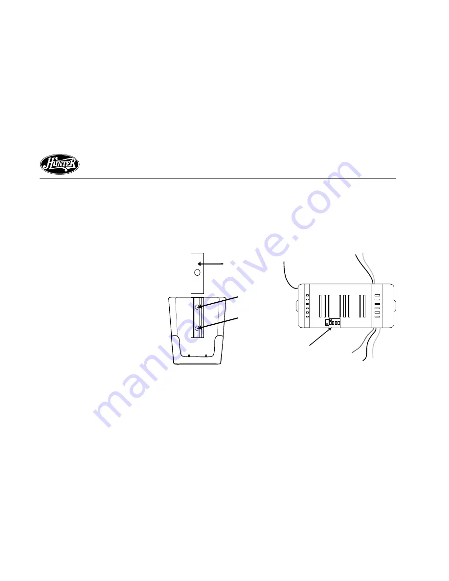
5. Mount the remote holder using
the two screws provided with the
remote kit. Slide out center piece
on the holder to see screw holes.
Replace center piece after mount-
ing to wall. Refer to Figure 6b.
6. The transmitter can be placed on
the remote holder for conve-
nience or safe-keeping.
INSTALLING THE RECEIVER
1. Slide the dip switches to the same
on/off position as the transmitter
using a ball-point pen or small-
head screwdriver. Refer to Figure
6c.
Figure 6b - Mounting the Remote
Holder
Figure 6c - Setting the Code on the
Receiver
ON
1 2 3 4
ON
Dip Switches
Screw Hole
Screw Hole
Screw Hole
Cover
Summary of Contents for 41457-01
Page 2: ...2 41457 01 7 2000 ...


