


41844-01 12/20/2002
© 2002 Hunter Fan Company
4
44
4
4
cutting the ceiling hole
1.
Locate the site for the hole directly below the joist or support
brace that will hold the outlet box and fan.
2.
Cut a 4" diameter hole through the drywall or plaster of the
ceiling as shown in Figure 5. You will use the hole to install the
support brace and outlet box.
F
FF
FFiiiiig
gg
ggur
ur
ur
ur
ure 5 - C
e 5 - C
e 5 - C
e 5 - C
e 5 - Cu
u
u
u
uttttttttttin
in
in
in
ing t
g t
g t
g t
g th
h
h
h
he c
e c
e c
e c
e ce
ee
eeilin
ilin
ilin
ilin
iling h
g h
g h
g h
g ho
o
o
o
ollllle
ee
ee
installing the support brace
If there is a ceiling joist directly above the hole which will allow the
outlet box to be recessed a minimum of 1/16" in the ceiling, go to
in
in
in
in
insssssttttta
aa
aallin
llin
llin
llin
lling t
g t
g t
g t
g th
h
h
h
he o
e o
e o
e o
e ou
u
u
u
utttttllllle
ee
eet b
t b
t b
t b
t bo
o
o
o
ox
xx
xx section.
If there is not an adequate ceiling joist available, do the following:
1.
Attach a 2" x 4" support brace between two joists. The sup-
port brace must allow the bottom of the outlet box to be re-
cessed a minimum of 1/16" into the ceiling. See Figure 6.
2.
Check the support brace to ensure it will support the full weight
of the fan and light kit.
installing the outlet box
1.
Obtain a UL-approved octagonal 4" x 1-1/2" outlet box, plus
two #8 x 1-1/2" wood screws and washers, available from any
hardware store or electrical supply house.
2.
Orient the outlet box so that both the inner and outer holes in
the box align with the joist or support brace.
3.
Drill pilot holes no larger than the minor diameter of the wood
screws (5/64") through the inner holes of the outlet box.
4.
Attach the outlet box directly to the support brace or joist
with two #8 x 1-1/2" wood screws and washers. The bottom of
the outlet box must be recessed a minimum of 1/16" into the
ceiling as shown in Figure 6.
F
FF
FFiiiiig
gg
ggur
ur
ur
ur
ure 7 - I
e 7 - I
e 7 - I
e 7 - I
e 7 - In
n
n
n
nsssssttttta
aa
aallin
llin
llin
llin
lling t
g t
g t
g t
g th
h
h
h
he o
e o
e o
e o
e ou
u
u
u
utttttllllle
ee
eet b
t b
t b
t b
t bo
o
o
o
ox
xx
xx
preparing the wiring
C
C
C
C
CA
A
A
A
AU
U
U
U
UT
T
T
T
TIIIIIO
O
O
O
ON: A
N: A
N: A
N: A
N: All w
ll w
ll w
ll w
ll wir
ir
ir
ir
irin
in
in
in
ing mu
g mu
g mu
g mu
g mussssst b
t b
t b
t b
t be in a
e in a
e in a
e in a
e in acccccccccco
o
o
o
orrrrrd
d
d
d
da
aa
aan
n
n
n
nccccce w
e w
e w
e w
e wiiiiittttth n
h n
h n
h n
h na-
a-
a-
a-
a-
tttttiiiiio
o
o
o
on
n
n
n
na
aa
aal a
l a
l a
l a
l an
n
n
n
nd l
d l
d l
d l
d lo
o
o
o
occccca
aa
aal e
l e
l e
l e
l ellllle
ee
eeccccctttttrrrrriiiiicccccaaaaal c
l c
l c
l c
l co
o
o
o
od
d
d
d
de
ee
ees a
s a
s a
s a
s an
n
n
n
nd A
d A
d A
d A
d AN
N
N
N
NS
SS
SSI/N
I/N
I/N
I/N
I/NF
FF
FFP
P
P
P
PA 70. I
A 70. I
A 70. I
A 70. I
A 70. If y
f y
f y
f y
f yo
o
o
o
ou
u
u
u
u
a
aa
aarrrrre un
e un
e un
e un
e unfffffa
aa
aam
m
m
m
mili
ili
ili
ili
ilia
aa
aar w
r w
r w
r w
r wiiiiittttth w
h w
h w
h w
h wir
ir
ir
ir
irin
in
in
in
ing
gg
gg, y
, y
, y
, y
, yo
o
o
o
ou s
u s
u s
u s
u sh
h
h
h
ho
o
o
o
oul
ul
ul
ul
uld u
d u
d u
d u
d ussssse a q
e a q
e a q
e a q
e a qu
u
u
u
ua
aa
aali
li
li
li
lifffffiiiiie
ee
eed e
d e
d e
d e
d ellllle
ee
eeccccc-----
tttttrrrrriiiiic
cc
cciiiiiaaaaan
n
n
n
n.....
1.
Make sure the circuit breakers to the fan supply line leads and
associated wall switch location are turned off. If you cannot
lock the circuit breakers in the off position, securely fasten a
prominent warning device, such as a tag, to the service panel.
2.
Thread the fan supply line through the outlet box so that the
fan supply line extends at least 6" beyond the box as shown in
Figure 7.
3.
Attach the fan supply line to the outlet box with an approved
connector, available at any hardware store or electrical supply
house. Refer to Figure 7.
4.
Make certain the wiring meets all national and local standards
and ANSI/NFPA 70.
F
FF
FFiiiiig
gg
ggur
ur
ur
ur
ure 7 - Pr
e 7 - Pr
e 7 - Pr
e 7 - Pr
e 7 - Pre
ee
eep
p
p
p
pa
aa
aarrrrrin
in
in
in
ing t
g t
g t
g t
g th
h
h
h
he w
e w
e w
e w
e wir
ir
ir
ir
irin
in
in
in
ing
gg
gg
You have now successfully prepared your ceiling fan site. For in-
structions on how to install your ceiling fan, continue with the in-
in-
in-
in-
in-
sssssttttta
aa
aallin
llin
llin
llin
lling t
g t
g t
g t
g th
h
h
h
he c
e c
e c
e c
e ce
ee
eeilin
ilin
ilin
ilin
iling p
g p
g p
g p
g pllllla
aa
aattttteeeee section.
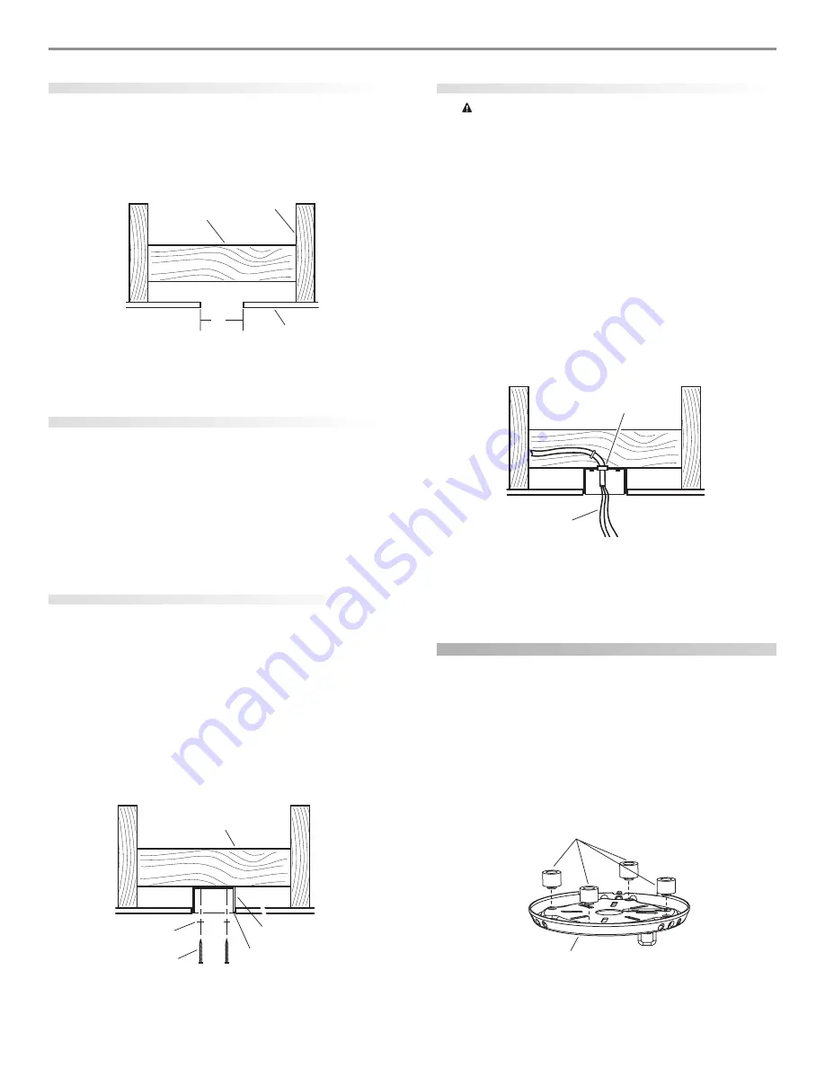
installing the ceiling plate
1.
Drill two pilot holes into the wood support structure through
the outermost holes on the outlet box. The pilot holes should
be 9/64" in diameter.
2.
Thread the lead wires from the outlet box through the hole in
the middle of the ceiling plate.
3.
Your fan comes with four neoprene noise isolators. Position
the isolators between the ceiling plate and ceiling by inserting
the raised areas on each isolator into the holes in the ceiling
plate. Refer to Figure 8.
F
FF
FFiiiiig
gg
ggur
ur
ur
ur
ure 8 - I
e 8 - I
e 8 - I
e 8 - I
e 8 - In
n
n
n
nssssse
ee
eerrrrrtttttin
in
in
in
ing t
g t
g t
g t
g th
h
h
h
he i
e i
e i
e i
e issssso
o
o
o
ollllla
aa
aattttto
o
o
o
orrrrrs in
s in
s in
s in
s inttttto t
o t
o t
o t
o th
h
h
h
he c
e c
e c
e c
e ce
ee
eeilin
ilin
ilin
ilin
iling p
g p
g p
g p
g pllllla
aa
aattttteeeee
4”
Diameter
Ceiling
Hole
Ceiling
Ceiling Joist
Support Brace
Support Brace
Outlet Box
1/16” Recess
Washer
Wood Screw
Approved
Connector
Wire Leads
Isolators
Ceiling Plate


