


41844-01 12/20/2002
© 2002 Hunter Fan Company
6
66
6
6
A
A
A
A
All w
ll w
ll w
ll w
ll wir
ir
ir
ir
irin
in
in
in
ing mu
g mu
g mu
g mu
g mussssst b
t b
t b
t b
t be in a
e in a
e in a
e in a
e in acccccccccco
o
o
o
orrrrrd
d
d
d
da
aa
aan
n
n
n
nccccce w
e w
e w
e w
e wiiiiittttth n
h n
h n
h n
h na
aa
aatttttiiiiio
o
o
o
on
n
n
n
na
aa
aal a
l a
l a
l a
l an
n
n
n
nd l
d l
d l
d l
d lo
o
o
o
occccca
aa
aalllll
e
ee
eellllleeeeeccccctttttrrrrriiiiicccccaaaaal c
l c
l c
l c
l co
o
o
o
od
d
d
d
de
ee
ees a
s a
s a
s a
s an
n
n
n
nd A
d A
d A
d A
d AN
N
N
N
NS
SS
SSI/N
I/N
I/N
I/N
I/NF
FF
FFP
P
P
P
PA 70. I
A 70. I
A 70. I
A 70. I
A 70. If y
f y
f y
f y
f yo
o
o
o
ou a
u a
u a
u a
u arrrrre un
e un
e un
e un
e unfffffa
aa
aam
m
m
m
mili
ili
ili
ili
ilia
aa
aarrrrr
w
w
w
w
wiiiiittttth w
h w
h w
h w
h wir
ir
ir
ir
irin
in
in
in
ing
gg
gg, y
, y
, y
, y
, yo
o
o
o
ou s
u s
u s
u s
u sh
h
h
h
ho
o
o
o
oul
ul
ul
ul
uld u
d u
d u
d u
d ussssse a q
e a q
e a q
e a q
e a qu
u
u
u
ua
aa
aali
li
li
li
lifffffiiiiie
ee
eed e
d e
d e
d e
d ellllle
ee
eeccccctttttrrrrriiiiiccccciiiiiaaaaan
n
n
n
n.....
F
FF
FFiiiiig
gg
ggur
ur
ur
ur
ure 13 - W
e 13 - W
e 13 - W
e 13 - W
e 13 - Wir
ir
ir
ir
irin
in
in
in
ing t
g t
g t
g t
g th
h
h
h
he f
e f
e f
e f
e fa
aa
aan
n
n
n
n
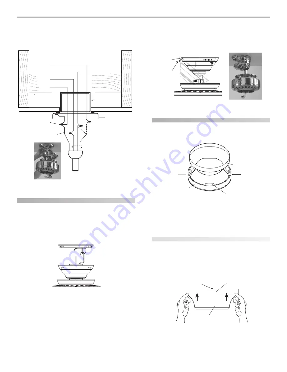
installing the canopy
1.
Rotate the fan 180º clockwise from the initial position when
hanging the fan. The arrows on the hanger ball and on the
ceiling plate should be pointing in the same direction and
should be pointing towards the tab hole on the canopy. Refer
to Figure 14.
F
FF
FFiiiiig
gg
ggur
ur
ur
ur
ure 14 - R
e 14 - R
e 14 - R
e 14 - R
e 14 - Ro
o
o
o
ottttta
aa
aatttttin
in
in
in
ing t
g t
g t
g t
g th
h
h
h
he f
e f
e f
e f
e fa
aa
aan
n
n
n
n
2.
Hook the tab hole over the tab on the ceiling plate as shown in
Figure 15.
3.
Raise the canopy, be sure the holes in the canopy and the ceil-
ing plate are aligned, and loosely assemble the canopy screws
one at a time. When all three screws are assembled, securely
tighten all three canopy screws. Refer to Figure 15.
F
FF
FFiiiiig
gg
ggur
ur
ur
ur
ure 15 - I
e 15 - I
e 15 - I
e 15 - I
e 15 - In
n
n
n
nsssssttttta
aa
aallin
llin
llin
llin
lling t
g t
g t
g t
g th
h
h
h
he c
e c
e c
e c
e ca
aa
aan
n
n
n
no
o
o
o
op
p
p
p
pyyyyy
installing the canopy trim ring
1.
To easily install the canopy trim ring, locate the two tabs on
the canopy trim ring. See Figure 16.
F
FF
FFiiiiig
gg
ggur
ur
ur
ur
ure 16 - C
e 16 - C
e 16 - C
e 16 - C
e 16 - Ca
aa
aan
n
n
n
no
o
o
o
op
p
p
p
py t
y t
y t
y t
y trrrrrim r
im r
im r
im r
im rin
in
in
in
ing
gg
gg
2.
Take both hands and push the canopy trim ring up to the top
of the canopy. See Figure 16.
3.
The canopy trim ring will snap and lock into place on the
canopy.
removing the canopy trim ring
1.
Locate the tab indicators, small bumps on top of tabs. Refer to
Figure 17.
2.
To remove the canopy trim ring, press firmly on opposite sides
of the ring towards the canopy as shown in Figure 17. The tabs
will flex out releasing the trim ring from the canopy.
F
FF
FFiiiiig
gg
ggur
ur
ur
ur
ure 17 - R
e 17 - R
e 17 - R
e 17 - R
e 17 - Re
ee
eem
m
m
m
mo
o
o
o
ov
vv
vvin
in
in
in
ing t
g t
g t
g t
g th
h
h
h
he c
e c
e c
e c
e ca
aa
aan
n
n
n
no
o
o
o
op
p
p
p
py t
y t
y t
y t
y trrrrrim r
im r
im r
im r
im rin
in
in
in
ing
gg
gg
Canopy
Canopy
Trim Ring
Tab
Press Here when
Removing
Press Here when
Removing
Canopy Trim Ring
Canopy
Tab Indicator
Wall Switch Wire for Separate
Control of Light Fixture
(Note: Wall
switch must be
acceptable as a
general-use
switch.)
Power
Wires
in
Ceiling
Black
White
Bare or Green
2 x 4 Brace
Outlet Box
Ceiling Plate
Approved
Connectors
Green Ground Wire from
Hanger Pipe (not present
with flush mounting
option)
Connections:
1. Connect Blk/Wht
wire from the fan to the
wall switch for separate
control of the light
fixture, or
2. Connect Blk/Wht
wire from the fan to the
ceiling black wire if there
is no separate wall
switch wire for the light
fixture.
Blk/Wht
3 Wires
from Fan
Wh
it
e
Bl
a
ck
1
2
Tab Hole
and Tab
Canopy
Screw


