background image

© 2005 Hunter Fan Company

41892-01  03/17/2005

7

2.

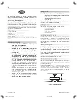
Hook the tab hole over the tab on the ceiling plate as shown in
Figure 17.

3.

Raise the canopy, be sure the holes in the canopy and the ceil-
ing plate are aligned, and loosely assemble the canopy screws
one at a time.  When all three screws are assembled, securely
tighten all three canopy screws.  Refer to Figure 17.

Figure 17 - Installing the canopy

installing the canopy trim ring

1.

To easily install the canopy trim ring, locate the two tabs on
the canopy trim ring.  See Figure 18.

Figure 18 - Canopy trim ring

2.

Take both hands and push the canopy trim ring up to the top
of the canopy.  See Figure 18.

3.

The canopy trim ring will snap and lock into place on the
canopy.

removing the canopy trim ring

1.

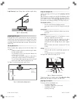
Locate the tab indicators, small bumps on top of tabs.  Refer
to Figure 19.

2.

To remove the canopy trim ring, press firmly on opposite sides
of the ring towards the canopy as shown in Figure 19.  The tabs
will flex out releasing the trim ring from the canopy.

Figure 19 - Removing the canopy trim ring

assembling the blades

Hunter fans use several styles of fan blade irons (brackets that hold
the blade to the fan).
1.

Your fan may include blade grommets. If your fan has grom-
mets, insert them by hand into the holes on the blades as shown
in Figure 20.

Figure 20 - Inserting the grommets into the fan blades

2.

Attach each blade to blade iron using three blade assembly
screws as shown in Figure 21.

Figure 21 - Attaching the blade to the blade iron

Tab Hole
and Tab

Canopy
Screw

Grommet

Fan Blade

Canopy Trim Ring

Canopy

Tab Indicator

Canopy

Canopy
Trim Ring

Tab

Press Here when
Removing

Press Here when
Removing

41892-01_Rev 03.17.05.pmd

3/18/05, 8:44 PM

7

Summary of Contents for 41892

Page 1: ...2005 Hunter Fan Company 41892 01 03 17 2005 1 41892 01_Rev 03 17 05 pmd 3 18 05 8 44 PM 1...

Page 2: ...ng or cleaning the fan Never insert foreign objects be tween rotating fan blades To reduce the risk of fire electrical shock or motor damage do not use a solid state speed control with this fan Use on...

Page 3: ...you can not check off every item see the preparing a new fan site section for instructions on properly preparing the site for your new fan fan support system Fan must attach directly to building stru...

Page 4: ...reparing the wiring CAUTION All wiring must be in accordance with na tional and local electrical codes and ANSI NFPA 70 If you are unfamiliar with wiring you should use a qualified elec trician 1 Make...

Page 5: ...r motor housing over the adapter as shown in Figure 12 Align the holes in the upper motor housing with the holes in the adapter 5 Partially install the three motor housing screws NOTE Make sure the ga...

Page 6: ...twist the bare metal leads together Place a wire nut over the intertwined length of wire and twist clockwise until tight as CAUTION Be sure no bare wire or wire strands are vis ible after making conn...

Page 7: ...1 Locate the tab indicators small bumps on top of tabs Refer to Figure 19 2 To remove the canopy trim ring press firmly on opposite sides of the ring towards the canopy as shown in Figure 19 The tabs...

Page 8: ...assembly See Fig ure 24 NOTE Both plug connectors are polarized and will only fit together one way Make sure that both connectors are prop erly aligned before connecting them together Incorrect con n...

Page 9: ...d but never use abrasive cleaning agents as they will damage the finish caringforblades Wood finish blades should be cleaned with a furniture polishing cloth Occasionally a light coat of furniture pol...

Reviews: