Hunter 50cc • AC Electric Systems
8.4
DANGER
!
!
Fuel leaking from any part of the fuel system can
lead to fire and explosion that can cause serious
bodily injury or death. Inspect system before start-
ing engines.
DANGER
!
!
Never enter the engine compartment without proper
ventilation first. A spark caused by power tools or
lighting equipment could result in fire or explosion
which could cause personal injury or death.
DANGER
!
!
As with any fuel burning engine, Carbon Monoxide
is a concern. Read the Boating Safety section of
this manual, and educate yourself about Carbon
Monoxide poisoning. It could mean the difference in
your life and the life of your loved ones.
For the more details on operating instructions, mainte-
nance instructions of the generator, please refers to the
generator owner’s manual.
8.1.7 Breakers, Switches, and Fuses
All electrical systems aboard your boat are provided with
over-current protection in the form of breakers or fuses.
Examples of breakers are the system or component con-
trols at the Main Distribution Panel, or MDP Systems that
would normally require you to energize them for use and
are provided with switches.
The breaker and switch panels are detailed further in the
end of this section under “Legends.”
8.1.9 Outlets and GFI Components
The outlets aboard your boat are for AC electrical con-
nections to supply power to your AC accessories. They
are just like your outlets in your home and supply 110 volt
(230 volt overseas) AC power.
There are 2 required GFI outlets aboard your boat. One
is in the galley, one at the Nav station. Though there are
several other outlets, they are wired in the circuit of an
existing GFI. The other outlet such as the one that sup-
plies power to your microwave receives power from the
MDP and breaker protected at that point. These are usu-
ally placed behind cabinets or the components that they
supply power to and aren’t visible.
Though the outlets are a system or a component such
as in the next subject, we have placed the descriptions
in the Power Supply subject due to the purpose of their
installation.
As with the DC System, there are several AC powered
systems or components aboard your boat. Here we will
break those down for you with a function and description
of each one. Later in the Operations and Maintenance
section, we will describe the use or operation of these
systems or components.
8.2 Systems and Components.
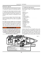
8.2.1 Inverter (option)
The inverter locates in main cabin starboard bunk.
Typically, there are two modes of operation associated
with an inverter/charger:
Inverter Mode:
Direct current (DC) from the boat’s batteries is trans-
formed into alternating current (AC) for use with you
household electrical appliances.
Charger Mode:
Alternating current (AC) is taken directly from shore
power (or other AC sources) and passed directly to your
household appliances. At the same time, the incoming
AC is also converted to DC to recharge the boat’s bat-
teries.
F
Summary of Contents for 50CC
Page 1: ...Operator s Operator s Manual Manual Hunter 5 Hunter 50 0cc cc ...
Page 2: ......
Page 9: ...Introduction Introduction Hunter 50cc Hunter 50cc Chapter 1 Chapter 1 ...
Page 14: ...Hunter 50cc Introduction 1 6 Notes ...
Page 15: ...Documents Documents Forms Forms Hunter 50cc Hunter 50cc Chapter 2 Chapter 2 ...
Page 26: ...Hunter 50CC Documents and Forms Maintenance Log Date Maintenance Performed Hourmeter 2 12 ...
Page 27: ...Hunter 50CC Documents and Forms 2 13 Date Maintenance Performed Hourmeter Maintenance Log ...
Page 33: ...Hunter 50CC Documents and Forms 2 19 Spare Parts List ...
Page 34: ...Hunter 50CC Documents and Forms Dates of practice drills and onboard safety inspections 2 20 ...
Page 36: ...Hunter 50CC Documents and Forms Notes 2 22 ...
Page 37: ...DC 071609 Limited Limited Warranty Warranty Chapter 3 Chapter 3 ...
Page 38: ...This Page Intentionally Left Blank Hunter Limited Warranty 3 2 ...
Page 47: ...Boating Safety Boating Safety Hunter 50cc Hunter 50cc Chapter 4 Chapter 4 ...
Page 66: ...Hunter 50CC Boating Safety 4 20 Notes ...
Page 67: ...Fuel Systems Fuel Systems Hunter 50cc Hunter 50cc Chapter 5 Chapter 5 ...
Page 73: ...Fig 5 7 A Quick Fuel Filter Reference Hunter 50CC Fuel Systems 5 7 ...
Page 81: ...Underwater Underwater Gear Gear Hunter 50cc Hunter 50cc Chapter 6 Chapter 6 ...
Page 92: ...Hunter 50CC Underwater Gear 6 12 Notes ...
Page 93: ...DC Electrical DC Electrical Systems Systems Hunter 50cc Hunter 50cc Chapter 7 Chapter 7 ...
Page 104: ...NAV LIGHT BREAKER DECK LIGHT BEAKER D Hunter 50CC DC Electric 7 12 ...
Page 105: ...AC Electric AC Electric Systems Systems Hunter 50cc Hunter 50cc Chapter 8 Chapter 8 ...
Page 114: ...Hunter 50cc AC Electric Systems 8 10 Notes ...
Page 115: ...Water Systems Water Systems Hunter 50cc Hunter 50cc Chapter 9 Chapter 9 ...
Page 127: ...Waste Waste Systems Systems Hunter 50cc Hunter 50cc Chapter 10 Chapter 10 ...
Page 140: ...Notes Hunter 50CC Waste and Sanitation Systems 10 14 ...
Page 150: ...Hunter 50CC Engines and Transmissions 11 10 Notes ...
Page 151: ...Sails Sails and and Riggings Riggings Hunter 50cc Hunter 50cc Chapter 12 Chapter 12 ...
Page 164: ...12 14 CAMCLEAT 1 2 5 4 11 3 2 12 7 8 9 10 6 50cc DUAL END MAINSHEET PURCHASE ARRANGEMENT ...
Page 175: ...Hunter 50cc Hunter 50cc Getting Getting Underway Underway Chapter 13 Chapter 13 ...
Page 182: ...Hunter 50CC Getting Underway 13 8 Notes ...
Page 183: ...Maintenance Chapter 14 Chapter 14 Hunter 50cc Hunter 50cc ...
Page 195: ...Glossary Glossary Chapter 15 Chapter 15 Hunter 50cc Hunter 50cc ...


