Hunter 50cc • AC Electric Systems
8.6
system.
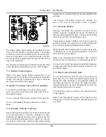
Fig. 8.4 shows one of
three air conditioning
unit wired remote control
panels. for more detail in-
formation, please refer to
the A/C owner’s manual
It is very important for you to read and understand the
operation and the maintenance for the systems or com-
ponents in your AC Electric System. This will save failure
of components or systems, as well as, make your boat a
safer, more enjoyable investment.
CAUTION
!
!
Always make certain that the pick-up and discharge
valves for the Air Conditioning System are opened
before using. Failure to do so will cause permanent
damage to your compressor. Also, be certain that
the strainer is clean. See the Water Systems section
for details on cleaning the Strainers.
8.3 Operations and Maintenance
8.3.1 To Operate the AC Electrical System
If you opted for the generator system, then you will, as we
have mentioned, have the capabilities for two separate
AC Electric systems. We will discuss the procedures for
energizing both.
CAUTION
!
!
DO NOT LEAVE THE BOAT UNATTENTED WHEN
SHORE POWER IS CONNECTED OR CHARGING
BATTERIES
8.3.2 Shore Power
First the Shore Power System is a convenient way to
obtain power should you be docked. Be sure to read the
warnings posted earlier in this section on shore power
safety.
1. Turn off shore power / generator selector on the
breaker panel.
2. Shut down the generator if it is in operation.
3. Connect the female end of the shore power cord to
your boat’s shore power inlet receptacle. Be certain that
the lock ring is tightly secure. If there is a cord already
supplied at the dock be sure to unhook the cord from the
dockside outlet.
4. Connect the shore power cable to the power supply.
When connecting the shore power cable to the dockside
outlet, be sure to make certain that the cable has suffi-
cient slack to prevent stretching during tidal changes.
Fig. 8.5
the stainless
shore power connector
located on transom port
side next to mooring cleat.
the upper connector is
for AC connection, and
the lower connector is for
TV antenna connection.
5. Select shore power on the breaker panel.
If there is no power to the electrical distribution panel
(MDP), check the following:
* Breaker switch at dockside power.
* Main breaker switch located in the aft cabin.
8.3.3 To Disconnect the Shore Power:
1. Turn off shore power / generator selector on the aft
breaker panel which located in the rudder post compart-
ment.
2. Turn off the dockside breaker.
3. Disconnect the shore power cord from the dockside
outlet.
4. Disconnect the shore power cord from the boat’s shore
power connection.
5. Store your cord in a safe, dry location.
DANGER
!
!
Summary of Contents for 50CC
Page 1: ...Operator s Operator s Manual Manual Hunter 5 Hunter 50 0cc cc ...
Page 2: ......
Page 9: ...Introduction Introduction Hunter 50cc Hunter 50cc Chapter 1 Chapter 1 ...
Page 14: ...Hunter 50cc Introduction 1 6 Notes ...
Page 15: ...Documents Documents Forms Forms Hunter 50cc Hunter 50cc Chapter 2 Chapter 2 ...
Page 26: ...Hunter 50CC Documents and Forms Maintenance Log Date Maintenance Performed Hourmeter 2 12 ...
Page 27: ...Hunter 50CC Documents and Forms 2 13 Date Maintenance Performed Hourmeter Maintenance Log ...
Page 33: ...Hunter 50CC Documents and Forms 2 19 Spare Parts List ...
Page 34: ...Hunter 50CC Documents and Forms Dates of practice drills and onboard safety inspections 2 20 ...
Page 36: ...Hunter 50CC Documents and Forms Notes 2 22 ...
Page 37: ...DC 071609 Limited Limited Warranty Warranty Chapter 3 Chapter 3 ...
Page 38: ...This Page Intentionally Left Blank Hunter Limited Warranty 3 2 ...
Page 47: ...Boating Safety Boating Safety Hunter 50cc Hunter 50cc Chapter 4 Chapter 4 ...
Page 66: ...Hunter 50CC Boating Safety 4 20 Notes ...
Page 67: ...Fuel Systems Fuel Systems Hunter 50cc Hunter 50cc Chapter 5 Chapter 5 ...
Page 73: ...Fig 5 7 A Quick Fuel Filter Reference Hunter 50CC Fuel Systems 5 7 ...
Page 81: ...Underwater Underwater Gear Gear Hunter 50cc Hunter 50cc Chapter 6 Chapter 6 ...
Page 92: ...Hunter 50CC Underwater Gear 6 12 Notes ...
Page 93: ...DC Electrical DC Electrical Systems Systems Hunter 50cc Hunter 50cc Chapter 7 Chapter 7 ...
Page 104: ...NAV LIGHT BREAKER DECK LIGHT BEAKER D Hunter 50CC DC Electric 7 12 ...
Page 105: ...AC Electric AC Electric Systems Systems Hunter 50cc Hunter 50cc Chapter 8 Chapter 8 ...
Page 114: ...Hunter 50cc AC Electric Systems 8 10 Notes ...
Page 115: ...Water Systems Water Systems Hunter 50cc Hunter 50cc Chapter 9 Chapter 9 ...
Page 127: ...Waste Waste Systems Systems Hunter 50cc Hunter 50cc Chapter 10 Chapter 10 ...
Page 140: ...Notes Hunter 50CC Waste and Sanitation Systems 10 14 ...
Page 150: ...Hunter 50CC Engines and Transmissions 11 10 Notes ...
Page 151: ...Sails Sails and and Riggings Riggings Hunter 50cc Hunter 50cc Chapter 12 Chapter 12 ...
Page 164: ...12 14 CAMCLEAT 1 2 5 4 11 3 2 12 7 8 9 10 6 50cc DUAL END MAINSHEET PURCHASE ARRANGEMENT ...
Page 175: ...Hunter 50cc Hunter 50cc Getting Getting Underway Underway Chapter 13 Chapter 13 ...
Page 182: ...Hunter 50CC Getting Underway 13 8 Notes ...
Page 183: ...Maintenance Chapter 14 Chapter 14 Hunter 50cc Hunter 50cc ...
Page 195: ...Glossary Glossary Chapter 15 Chapter 15 Hunter 50cc Hunter 50cc ...


