background image

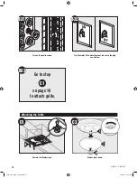
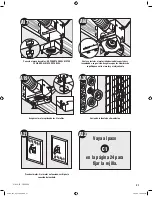
EXISTING FAN

B11

E

B12


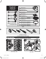
Existing Construction 

B13

2

1

B14

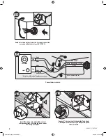
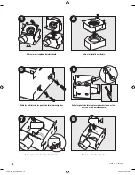
Route wires through the strain relief. For supply connection, 

use wires suitable for at least 90˚ C (194˚ F).

Remove an existing fan and check to make sure the open-

ing is large enough to accommodate the new motor hous-

ing (7.25” x 7.75”).

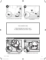
Move the housing into position above the ceiling.

Attach existing ducting to duct connector. Tape joints.

If ducting does not fit securely,

an adapter may need to be purchased.

E

B15

Install the housing flush with the sheetrock and secure by 

tightening the pre-loaded screws into the joist.

8


41938-01   3/29/2006 


41938-01   3/29/2006

05-HF-024_EngS_3.29.06.indd   8

3/29/06   7:25:27 PM

Summary of Contents for Ashbury 81002

Page 1: ...l a t i o n G u i d e 81002 81005 Ashbury Bath Ventilator with Light READ and SAVE THESE INSTRUCTIONS 41938 01 3 29 2006 ENGLISH See page 2 Español Vea la página 15 05 HF 024_EngS_3 29 06 indd 1 3 29 06 7 25 12 PM ...

Page 2: ... OF ELECTRIC SHOCK OR INJURY OBSERVE THE FOLLOWING 1 Use this unit only in a manner intended by the manufacturer If you have questions contact the manufacturer at the phone number or address listed in the warranty 2 Before installing servicing or cleaning the unit disconnect the power by turning off the circuit breakers to the outlet box and associated wall switch location If you cannot lock the c...

Page 3: ...ector must be installed Not Included A B C Extra Screws x2 D E F G 95047 03 000 75864 01 000 03242 07 133 3 8 Cable Connector 3 1 Turn off the power source Tools Needed Not supplied Estimated assembly time 30 to 60 minutes Before Installation Check all the parts If damaged call 1 888 830 1326 for replacements 2 E I Loosen screws NOTE Remove all packing materials before installation 41938 01 3 29 2...

Page 4: ...Remove the pre loaded screw tip covers Remove the wiring cover screw 6 Back out the pre loaded screw tips until flush with the side of the housing Remove the wiring cover Remove packing material 41938 01 3 29 2006 05 HF 024_EngS_3 29 06 indd 4 3 29 06 7 25 17 PM ...

Page 5: ...pth mark at the bottom edge of the joist based on the thickness of your sheetrock New Construction 5 10 B C Choose Installation Option For New Construction go to step A11 page 5 For Existing Construction go to step B11 page 8 A11 E 5 8 1 2 5 8 1 2 A12 Screw pre loaded screws into joist or framing 41938 01 3 29 2006 05 HF 024_EngS_3 29 06 indd 5 3 29 06 7 25 19 PM ...

Page 6: ...res through the strain relief For supply connection use wires suitable for at least 90 C 194 F 0 0 A16 Connect 4 duct and vent to the outside Tape joints If ducting does not fit securely an adapter may need to be purchased 6 A15 E F G Install the wiring cover plate Make sure all wiring connections are inside the box or under the wiring cover plate 41938 01 3 29 2006 05 HF 024_EngS_3 29 06 indd 6 3...

Page 7: ...r by tightening the 2 screws Turn on the power source 7 Connect wiring harness DO NOT ALLOW THE MOTOR TO HANG FROM THE WIRING HARNESS 0 0 0 0 0 0 0 0 A17 0 0 0 0 0 0 0 0 H A18 ON OFF A21 Test the motor If the motor does not run check the plug connection A22 C1 Go to step on page 10 to attach grille 41938 01 3 29 2006 05 HF 024_EngS_3 29 06 indd 7 3 29 06 7 25 24 PM ...

Page 8: ...is large enough to accommodate the new motor hous ing 7 25 x 7 75 Move the housing into position above the ceiling Attach existing ducting to duct connector Tape joints If ducting does not fit securely an adapter may need to be purchased E B15 Install the housing flush with the sheetrock and secure by tightening the pre loaded screws into the joist 8 41938 01 3 29 2006 05 HF 024_EngS_3 29 06 indd ...

Page 9: ...THE MOTOR TO HANG FROM THE WIRING HARNESS Secure the motor by tightening the 2 screws A 3 Pin 2 Pin Fan Motor Light Light Green Black Black White Black Black White White Bare Copper Ground B16 Main Switch 1 AC In Switch 2 AC In Option Fan Main Light Together Option Connect wires as shown F B17 G Install the wiring cover plate 9 41938 01 3 29 2006 05 HF 024_EngS_3 29 06 indd 9 3 29 06 7 25 29 PM ...

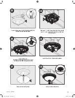
Page 10: ... grille B21 Test the motor If the motor does not run check the plug connection Turn on the power source J M C2 L K C1 Attaching the Grille Remove the thumbscrews Remove glass dome 10 41938 01 3 29 2006 05 HF 024_EngS_3 29 06 indd 10 3 29 06 7 25 32 PM ...

Page 11: ...umbscrews WARNING To reduce the risk of electrical shock all 3 thumbscrews MUST be properly installed Align glass dome and push up Install 2 Max 60 Watt A15 bulbs Not Included Screw glass dome into position C3 J Connect wiring harness DO NOT ALLOW THE FIXTURE TO HANG FROM THE WIRING HARNESS 11 41938 01 3 29 2006 05 HF 024_EngS_3 29 06 indd 11 3 29 06 7 25 35 PM ...

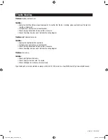
Page 12: ...t does not come on Solution Replace the light bulb with a new bulb Turn power on replace fuse or reset breaker Check all plug connections to be sure they are secure Check the wiring to make sure it matches the wiring diagram Problem Fan is noisy Solution Check and tighten all fasteners Check the glass to make sure it is secure Check the flapper to make sure it moves freely If you need parts or ser...

Page 13: ...TIES THE DURATION OF ANY IMPLIED WARRANTY INCLUDING BUT NOT LIMITED TO ANY IMPLIED WARRANTY OF MERCHANTABILITY OR FITNESS FOR A PARTICULAR PURPOSE IN RESPECT TO ANY HUNTER FAN BATH EXHAUST FAN MOTOR OR OTHER FAN PART IS EXPRESSLY LIMITED TO THE PERIOD OF THE EXPRESS WARRANTY SET FORTH ABOVE FOR SUCH MOTORS OR OTHER PARTS This warranty is voided if your Hunter bath exhaust fan is not purchased and ...

Page 14: ...2500 Frisco Avenue Memphis Tennessee 38114 Printed in China 41938 01 3 29 2006 14 2006 Hunter Fan Company 05 HF 024_EngS_3 29 06 indd 14 3 29 06 7 25 36 PM ...

Page 15: ...ESDE G u í a d e i n s t a l a c i ó n Ventilador para baño Ashbury 81002 y 81005 con luz LEA y CONSERVE ESTAS INSTRUCCIONES 41938 02 3 29 2006 15 Español 05 HF 024_Sp_3 29 06 indd 15 3 29 06 7 26 16 PM ...

Page 16: ...r el impulsor al mismo tiempo PRECAUCIÓN ADVERTENCIA A D V E R T E N C I A PARA REDUCIR EL RIESGO DE DESCARGA ELÉCTRICA O LESIONES OBSERVE LO SIGUIENTE 1 Utilice esta unidad sólo de la manera indicada por el fabricante Si tiene alguna pregunta contacte con el fabricante en el teléfono o la dirección indicados en la garantía 2 Antes de instalar dar servicio o limpiar la unidad desconecte la aliment...

Page 17: ... A B C x2 D E F G 95047 03 000 75864 01 000 03242 07 133 Conector de cable de 3 8 Tornillos adicionales 17 1 Incluido 2 E I Apague la fuente de alimentación Herramientas necesarias no suministradas Tiempo estimado de ensamblaje entre 30 y 60 minutos Antes de la instalación Verifique todos los componentes Si están dañados llame al 1 888 830 1326 para obtener un reemplazo Afloje los tornillos NOTA R...

Page 18: ...as de tornillo precargadas Retire el tornillo de la cubierta del cableado Retire las puntas de tornillo precargadas hasta que estén a nivel con el lado del alojamiento Retire la cubierta del cableado Retire el material de embalaje 41938 02 3 29 2006 05 HF 024_Sp_3 29 06 indd 18 3 29 06 7 26 21 PM ...

Page 19: ...mente con una arandela Ubique la correcta marca de profundidad en el borde inferior de la viga según el espesor de su plancha de yeso Construcción nueva Escoja la opción de instalación Para construcción nueva vaya al paso A11 página 19 Para construcción existente vaya al paso B11 página 22 Instale los tornillos precargados en la viga o el marco 41938 02 3 29 2006 05 HF 024_Sp_3 29 06 indd 19 3 29 ...

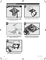
Page 20: ...livio de tension Para conexiones de alimentación use alambres adecuados al menos para 90º C 194º F Conecte los alambres como se muestra Conecte un ducto de 4 y ventile hacia el exterior Aplique cinta a las uniones Si el ducto no se ajusta firmemente puede ser necesario comprar un adaptador Instale la placa de cubierta del cableado Asegúrese que todas las conexiones de cableado estén dentro de la c...

Page 21: ...nte de alimentación Conecte el mazo de cables NO PERMITA QUE EL MOTOR CUELGUE DEL MAZO DE CABLES Vuelva a instalar el motor introduciendo las pestañas y levantando a su posición Asegúrese que los alambres no se pellizquen entre el motor y el alojamiento Pruebe el motor Si el motor no funciona verifique la conexión del enchufe 41938 02 3 29 2006 05 HF 024_Sp_3 29 06 indd 21 3 29 06 7 26 28 PM ...

Page 22: ... sea suficientemente grande para acomodar el alojamiento del motor nuevo 7 25 x 7 75 Mueva el alojamiento a su posición encima del techo Conecte el ducto existente con el conector de ducto Aplique cinta a las uniones Si el ducto no se ajusta firme mente puede ser necesario comprar un adaptador Instale el alojamiento a nivel con la plancha de yeso y asegúrelo apretando los tornillos precargados en ...

Page 23: ...ores 2 clavijas F B17 G Conecte los alambres como se muestra Vuelva a instalar el motor introduciendo las pestañas y levantando a su posición Asegúrese que los alambres no se pellizquen entre el motor y el alojamiento Conecte el mazo de cables NO PERMITA QUE EL MOTOR CUELGUE DEL MAZO DE CABLES Asegure el motor apretando los 2 tornillos Instale la placa de cubierta del cableado 23 41938 02 3 29 200...

Page 24: ...ejilla B21 J M C2 L K C1 Fijación de la rejilla Pruebe el motor Si el motor no funciona verifique la conexión del enchufe Encienda la fuente de alimentación Retire los tornillos de mano Retire la pantalla 24 41938 02 3 29 2006 05 HF 024_Sp_3 29 06 indd 24 3 29 06 7 26 36 PM ...

Page 25: ...e mano ADVERTENCIA Para reducir el riesgo de descarga eléctrica los 3 tornillos de mano DEBEN instalarse apropiadamente Alinee la pantalla y levante Instale 2 bombillas A 15 de 60 vatios como máximo No incluidas Enrosque la pantalla en su posición Conecte el mazo de cables NO PERMITA QUE EL ARTEFACTO DE ILUMINACIÓN CUELGUE DEL MAZO DE CABLES 25 41938 02 3 29 2006 05 HF 024_Sp_3 29 06 indd 25 3 29 ...

Page 26: ...do Problema La luz no funciona Solución Reemplace la bombilla con una nueva Encienda la alimentación eléctrica reemplace el fusible o restablezca el interruptor automático Verifique todas las conexiones de los enchufes para asegurarse que estén firmes Verifique el cableado para asegurarse que coincida con el diagrama de cableado Problema El ventilador hace ruido Solución Verifique y apriete todos ...

Page 27: ...E AIRE PARA BAÑO ESTA GARANTÍA SUSTITUYEATODAS LAS OTRAS GARANTÍAS EXPRESAS LA DURACIÓN DETODA GARANTÍA IMPLÍCITA INCLUYENDO PERO SIN LIMITARSE A CUALQUIER GARANTÍA IMPLÍCITA DE COMERCIABILIDAD O IDONEIDAD PARA UN PROPÓSITO PARTICULAR CON RESPECTO DE CUALQUIER MOTOR DE EXTRACTOR DE AIRE PARA BAÑO HUNTER U OTRA PARTE DEL VENTILADOR ESTÁ EXPRESAMENTE LIMITADA AL PERIODO DE LA GARANTIA EXPRESA ESTABL...

Page 28: ...2500 Frisco Avenue Memphis Tennessee 38114 Impreso en China 41938 02 3 29 2006 2006 Hunter Fan Company 05 HF 024_Sp_3 29 06 indd 28 3 29 06 7 26 40 PM ...

Reviews: