background image

Type T,G,B Models

Type T,G,B Models

Type T,G,B Models

Form# 41681-01

20100305

©2010 Hunter Fan Co.

For Your Records and

Warranty Assistance

For reference, also attach your receipt or a copy

of your receipt to the manual.

__________________________________________

Model Name

__________________________________________

Model No.

__________________________________________

Date Purchased

__________________________________________

Where Purchased

English

Francias

Owner’s Guide and Installation Manual

Summary of Contents for B

Page 1: ...nce also attach your receipt or a copy of your receipt to the manual __________________________________________ Model Name __________________________________________ Model No __________________________________________ Date Purchased __________________________________________ Where Purchased English Francias Owner s Guide and Installation Manual ...

Page 2: ...ur fan disconnect the power by turning off the circuit breakers to the outlet box and associated wall switch location If you cannot lock the circuit breakers in the off position securely fasten a prominent warning device such as a tag to the service panel All wiring must be in accordance with national and local electrical codes and ANSI NFPA 70 If you are unfamiliar with wiring use a qualified ele...

Page 3: ...ermine if the site is acceptable and safe for your new Hunter fan If you cannot check off every item prepare a new fan site as described on this page Fan Support System Fan attaches directly to building structure Fan support system will hold full weight of the fan and light kit Ceiling Hole e outlet box clearance hole is directly below the joist or support brace Outlet Box e outlet box is an UL ap...

Page 4: ... 1 2 outlet box plus two 8 x 1 1 2 wood screws and washers available from any hardware store or electrical supply house 4 2 Orient the outlet box so that both the inner and outer holes in the box align with the joist or support brace 4 3 Drill pilot holes no larger than the minor diameter of the wood screws 5 64 through the inner holes of the outlet box 4 4 Attach the outlet box directly to the su...

Page 5: ...es Consider using Hunter s optional accessories including a wall mounted or remote speed control To install and use the accessories follow the instructions included with each product For quiet and optimum performance of your Hunter fan use only Hunter speed controls Low Profile Mounting fits close to the ceiling recommended for ceilings less than 8 feet high Standard Mounting hangs from the ceilin...

Page 6: ...liers CheckingYourFanParts Carefully unpack your fan to avoid damage to the fan parts Check for any shipping damage to the motor or fan blades If one of the fan blades was damaged in shipment return all the blades for replacement If any parts are missing or damaged contact your Hunter dealer or call Hunter Parts Department at 866 268 1936 PreparingtheFanSite Before you begin installing the fan fol...

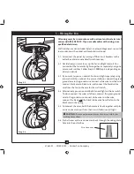
Page 7: ...the slotted holes in the ceiling plate with the pilot holes you drilled in the wood support structure For proper alignment use slotted holes directly across from each other Note The isolators should be flush against the ceiling 2 5 Place a flat washer on each of the two 3 screws and pass the screws through the slotted holes in the ceiling plate into the pilot holes you drilled Tighten the screws i...

Page 8: ... to Step 3 5 CAUTION The adapter has a special coating on the threads Do not remove this coating the coating prevents the downrod from unscrewing Once assembled do not remove the downrod 3 3 Place the low profile washer lip up into the canopy Be sure the green ground wire is pointing up toward the ceiling 3 4 Align the holes in the washer with the holes in the adapter Assemble securely with three ...

Page 9: ...er into the side of the brace that holds the outlet box Leave 3mm 1 8 of space between the support brace and the washer 4 4 Wrap the braided cable around the support brace once creating a complete circle 4 5 Hook the looped end of the cable over the wood screw so that the braided cable lies between the washer and the support brace 4 6 Tighten the loop and secure the screw and washer all the way do...

Page 10: ... separately using two wall switches connect the wires as follows connect the green ground wire to the ground wire connect white wire to white wire connect black wire to black wire and connect the black white wire from the fan to the wire for the wall switch 5 4 Alternatively you can control both fan and light with one switch To do so connect the wires as follows connect the green ground wire to th...

Page 11: ...e canopy one at a time Once all three screws are in tighten them 6 5 Using both hands push the canopy trim ring up to the top of the canopy The canopy trim ring will snap and lock into place 6 Installing the Canopy and Canopy Trim Ring Should you need to remove the canopy trim ring follow these steps 1 Locate the tab indicators small bumps on top of tabs 2 Press firmly on opposite sides of the rin...

Page 12: ...ree blade assembly screws If you used grommets the blades may appear slightly loose after screws are tightened This is normal 7 3 Remove the blade mounting screws and rubber shipping bumpers from the motor 7 4 For each blade insert one blade mounting screw through the blade iron and attach lightly to the fan Insert the second blade mounting screw then securely tighten both mounting screws Step 7 1...

Page 13: ... plate 8 2 Feed the upper plug connector through the center opening of the housing 8 3 Align the keyhole slots in the housing with the housing assembly screws 8 4 Turn the housing counterclockwise until the housing assembly screws are firmly situated in the narrow end of the keyhole slots Install the remaining 6 32 x 3 8 screw into the housing Tighten all three screws firmly CAUTION Make sure the ...

Page 14: ...housing to the upper switch housing with three 6 32 x 3 8 housing assembly screws If you are not installing the light fixture your installation is complete Otherwise proceed with step 8 8 8 8 The last installation step when installing the light fixture is to install the glass bowl See Installing the Glass Bowl on page 16 for instructions Lower Switch Housing Plug Connector Housing Assembly Screw P...

Page 15: ...nector male through first and then push the other plug connector female through the hole 4 Screw the threaded rod of the light fixture into the lower switch housing 5 Install the nut and washer from the end of the light fixture inside the lower switch housing 6 Connect the plug connectors between the two white wires 7 Connect the plug connectors between the black wire and black white wire Lower Sw...

Page 16: ...h the hole in the center of the glass bowl 4 Thread the light pull chain through the hole in the center of the glass bowl 5 Place the cover plate up against the glass bowl Align the holes in the cover plate and glass bowl 6 Thread the fan pull chain and light pull chain through the appropriate holes 7 Thread the light pull chain through the finial and screw the finial onto the threaded rod end unt...

Page 17: ... air upward clockwise blade rotation will distribute the warmer air trapped at the ceiling around the room without causing a draft 9 5 For cleaning finishes use a soft brush or lint free cloth to prevent scratching A vacuum cleaner brush nozzle can remove heavier dust Remove surface smudges or accumulated dirt and dust using a mild detergent and a slightly dampened cloth You may use an artistic ag...

Page 18: ...f so replace all the blades Problem Excessive wobbling 1 If your fan wobbles when operating use the enclosed balancing kit and instructions to balance the fan 2 Tighten all blade iron screws 3 Turn power off support fan very carefully and check that the hanger ball is properly seated Problem Lights dim when turned on or do not turn on 1 Check to make sure wattage of light bulbs installed match the...

Reviews: