background image

2500 Frisco Avenue, Memphis, Tennessee 38114

Printed in China


41788-01  6/1/2005 

Summary of Contents for Bath Ventilator Fan

Page 1: ...2500 Frisco Avenue Memphis Tennessee 38114 Printed in China 41788 01 6 1 2005 ...

Page 2: ...I n s t a l l a t i o n G u i d e 82500 Infiniti Bath Ventilator Fan 41788 01 6 1 2005 ...

Page 3: ...otor with the exact service motor You should replace the impeller at the same time C A U T I O N W A R N I N G 1 Use this unit only in a manner intended by the manufacturer If you have questions contact the manufacturer at the phone number or address listed in the warranty 2 Before installing servicing or cleaning the unit disconnect the power by turning off the circuit breakers to the outlet box ...

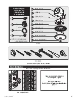
Page 4: ...ed call 1 888 830 1326 for replacements New construction installation Go to Step A1 page 4 Existing construction Go to Existing Construction Installation page 8 41788 01 6 1 2005 NOTE Remove all packing materials before installation x4 3 8 Cable Connector NOTE Strain relief cable connector must be installed Not Included A B C Extra Screws x2 H E D L 77864 02 F G H I J K 03242 07 133 96261 01 000 9...

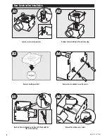
Page 5: ...th the side of the housing Remove the motor blower from the housing Remove the wiring cover screw 4 Remove packing material A2 A3 A6 F Loosen screw securing motor A4 A5 Remove the pre loaded screw tip covers New Construction Installation 41788 01 6 1 2005 ...

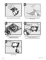
Page 6: ...elief into the housing and secure with the washer Position the correct depth mark at the bottom edge of the joist based on the thickness of your sheet rock Screw pre loaded screws into joist or framing Nail the tabs on both sides to joist or framing so that the housing will be flush with the finished ceiling Nails are not provided 5 41788 01 6 1 2005 ...

Page 7: ... Together Option D E A15 F Pull the wires through the strain relief Tighten the strain relief screws Connect wires as shown Connect a 4 duct and vent to the outside Tape joints If ducting does not fit securely an adapter may need to be purchased Install the wiring cover plate Make sure all wiring connections are inside the box or under the wiring cover plate 6 41788 01 6 1 2005 ...

Page 8: ... the wiring cover plate Reinstall the motor by inserting the tabs and pushing up into position Make sure the wires are not pinched between the motor and the housing Secure the motor by tightening the 2 screws Turn on the power source Test the motor If the motor does not run check the plug connection 7 A19 H 41788 01 6 1 2005 ...

Page 9: ...the opening is large enough to accommodate the new motor housing 7 25 x 7 75 Remove the motor blower from the housing Existing Construction Installation Existing Fan 8 Remove packing material D Use the motor housing as a template to mark position 41788 01 6 1 2005 Cut out an opening for the housing ...

Page 10: ...he side of the housing 9 B6 E B7 E Remove the wiring cover Remove the wiring cover screw Remove the pre loaded screw tip covers 41788 01 6 1 2005 Insert the strain relief into the housing and secure with the washer Pop out the first wiring access slug Use second if needed ...

Page 11: ...e sheetrock ceiling B11 2 1 B12 D B13 D B14 10 Pull the wires through the strain relief and tighten the strain relief screws Attach existing ducting to duct connector Tape joints If ducting does not fit securely an adapter may need to be purchased Move the housing into position above the ceiling 41788 01 6 1 2005 Connect the wiring ...

Page 12: ...B18 Install the wiring cover plate Make sure all wiring connections are inside the box or under the wiring cover plate Connect wiring from the motor to the wiring cover plate Reinstall the motor by inserting the tabs and pushing up into position Make sure the wires are not pinched between the motor and the housing 11 H B19 Secure the motor by tightening the 2 screws 41788 01 6 1 2005 Connect wires...

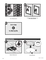
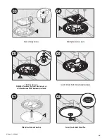
Page 13: ... C1 Go to step to attach grille 12 J C1 Test the motor If the motor does not run check the plug connection Turn on the power source Attaching the Grille C2 K L I 41788 01 6 1 2005 Remove the thumbscrews Remove glass dome ...

Page 14: ...sts Attach thumbscrews WARNING To reduce the risk of electrical shock all 3 thumbscrews MUST be properly installed I J C5 Install 2 Max 60 Watt A15 bulbs Not Included C6 Screw glass dome into position Align glass dome and push up K C7 L C8 41788 01 6 1 2005 13 ...

Page 15: ...ure it matches the wiring diagram Problem Light does not come on Solution Replace the light bulb with a new bulb Turn power on replace fuse or reset breaker Check all plug connections to be sure they are secure Check the wiring to make sure it matches the wiring diagram Problem Fan is noisy Solution Check and tighten all fasteners Check the glass to make sure it is secure Check the flapper to make ...

Page 16: ...F ALL OTHER EXPRESS WARRANTIES THE DURATION OF ANY IMPLIED WARRANTY INCLUDING BUT NOT LIMITED TO ANY IMPLIED WARRANTY OF MERCHANTABILITY OR FITNESS FOR A PARTICULAR PURPOSE IN RESPECT TO ANY HUNTER FAN BATH EXHAUST FAN MOTOR OR OTHER FAN PART IS EXPRESSLY LIMITED TO THE PERIOD OF THE EXPRESS WARRANTY SET FORTH ABOVE FOR SUCH MOTORS OR OTHER PARTS This warranty is voided if your Hunter bath exhaust...

Reviews: