background image

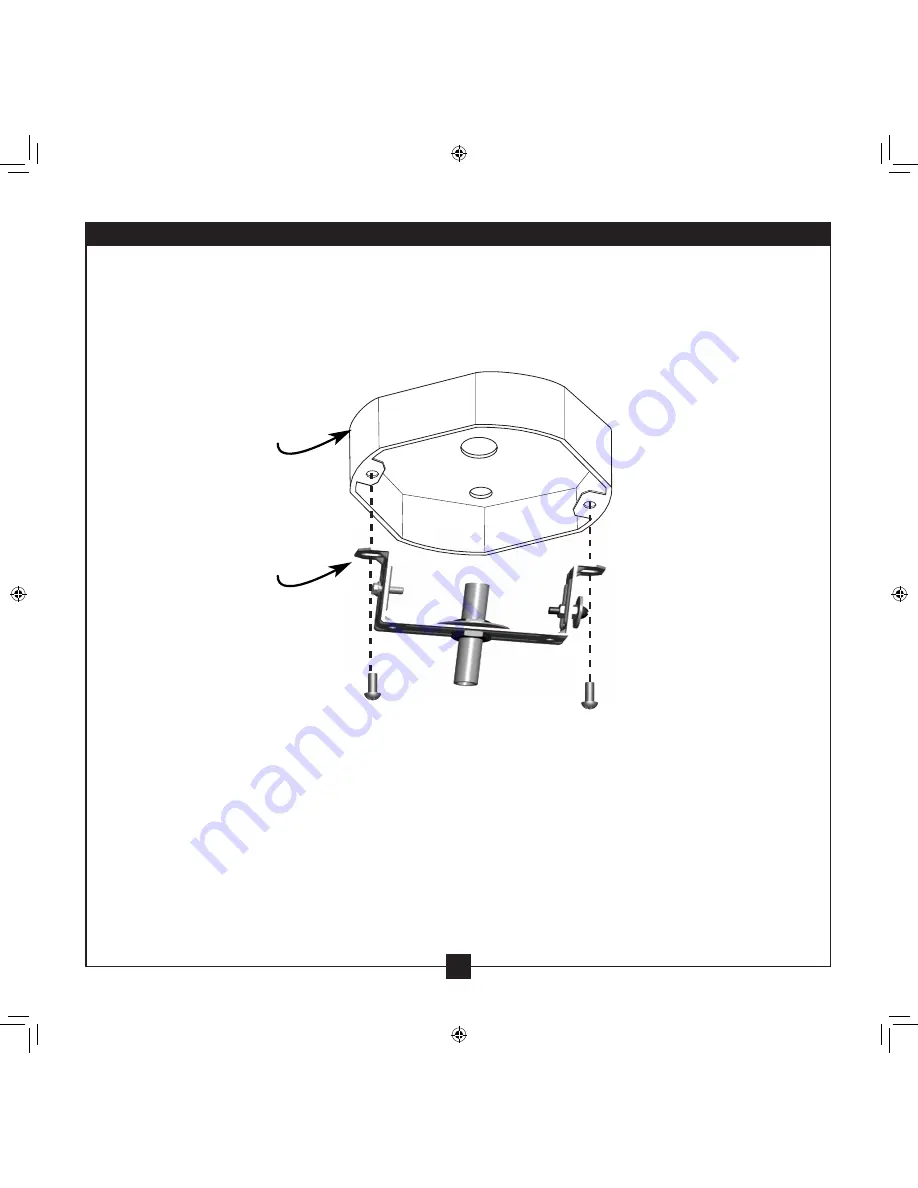
Figure 5 - Attach Hanger to Electrical Box

1) If you are replacing an existing light fixture, disconnect and remove the old fixture and 

  hanger bracket, leaving the exposed wires coming from the electrical box. 

2) Attach the Hanger Bracket assembly to the electrical box as shown in Figure 5.

Hanger Bracket

Electrical Box

6

43566-01  •  06/25/10  •  Hunter Fan Company

Installation

Summary of Contents for Illumi-Heat

Page 1: ...566 01 20100625 2010 Hunter Fan Co English Español Illumi Heat Light Heat on Demand Illumi Heat Light Heat on Demand Illumi Heat Light Heat on Demand Owner s Guide and Installation Manual Manual De Propietario ...

Page 2: ...d electrician Before you begin installing the fixture switch power off at the correct breaker turn on the bulb switch to make sure breaker handle was sitting on the right position and lock the breaker box to prevent power from being switched on accidentally during installation When the breaker box cannot be locked securely fasten a prominent warning device such as a danger tag to the breaker box T...

Page 3: ...n the box before installing Flat head screwdriver Phillips screwdriver Transmitter and Transmitter Holder not to scale Needle nosed Pliers Wires Black White Copper Ground Receiver Canopy Hanger Bracket Threaded Rod Light Sockets 3 Heater Light Fixture Top Finial 3 43566 01 06 25 10 Hunter Fan Company Parts ...

Page 4: ...iver as shown in Figure 1 Figure 1 Receiver 2 On the Receiver you will see the four switches that you will use to set the code for the Transmitter and the Receiver See Figure 2 ON DIP ON DIP Figure 2 Receiver Code Switches Switches NOTE All Switches are shown in the ON position ON DIP Receiver Bracket cut away for clarity 4 43566 01 06 25 10 Hunter Fan Company Pre Installation for Multiple Illumi ...

Page 5: ...very Receiver Code Switch you turned Off use a pair of needle nosed pliers to carefully remove its corresponding Connector from the Transmitter Terminals See Figure 4 For instance if you turned Off Receiver Switches 1 and 3 then you would remove Connectors 1 and 3 from the Transmitter 1 2 3 4 Transmitter Battery Compartment Door Transmitter Terminals Connector Figure 4 Transmitter Terminals and Co...

Page 6: ...fixture disconnect and remove the old fixture and hanger bracket leaving the exposed wires coming from the electrical box 2 Attach the Hanger Bracket assembly to the electrical box as shown in Figure 5 Hanger Bracket Electrical Box 6 43566 01 06 25 10 Hunter Fan Company Installation ...

Page 7: ...e Fixture Figure 7 Ground Screw Cable Loop Hanger Cable Loop 7 43566 01 06 25 10 Hunter Fan Company 4 Use UL approved wire connectors to connect the wires black to black white to white Loop the ground wires around the Ground Screw then tighten the Ground Screw See Figure 7 Ground Screw Installation Continued ...

Page 8: ...om of the canopy See Figure 8 Figure 8 Positioning the Fixture Swing fixture up INSTA L LAT ION cont inued Threaded Rod NOTE For clarity the electrical box and wires have been omitted from this illustration Canopy 8 43566 01 06 25 10 Hunter Fan Company Installation Continued ...

Page 9: ...gure 9 Top Finial Nut Installation INSTA L LAT ION cont inued Figure 10 Install Light Bulbs 7 Install three 40 watt Candelabra light bulbs not included as shown in Figure 10 40 watt Candelabra Light Bulbs not included Top Finial Threaded Rod 9 43566 01 06 25 10 Hunter Fan Company Installation Continued ...

Page 10: ...re 12 and twist it clock wise until tight Figure 12 Install Bottom Finial Glass Bottom Finial 8 Position the Glass Dome under the Heater Light Fixture as shown in Figure 11a Then place the Glass Dome over the Heater Light Fixture as shown in Figure 11b Install Glass Dome 10 43566 01 06 25 10 Hunter Fan Company Installation Continued ...

Page 11: ...t on and off See Figure 13 OFF OFF ON ON HEATER LIGHT Figure 13 Transmitter Buttons Heater Off Heater On Light Off Light On 4 Mount the Transmitter Holder over the Illumi Heat s wall switch using the the existing wall plate screws See Figure 14 5 The Transmitter can be placed in the Transmitter Holder for convenience or safekeeping Figure 14 Installing Transmitter Holder 11 43566 01 06 25 10 Hunte...

Page 12: ...ve it for better reception 2 Replace with new 12 Volt alkaline battery Problem Inconsistent operation 1 Extend antenna into ceiling box or move it for better reception 2 Turn OFF wall switch for 5 seconds then back ON 3 Change dip switch settings to a different code in both Transmitter and Receiver If you need parts or service assistance please call 888 830 1326 In Canada call 1 866 268 1936 or vi...

Reviews: