Waste and Sanitation Systems
10.1
tank or bilge pump, or a common drain fed from multiple
sources.
Thru-hulls are typically fitted to drain hoses or pipes
and sized to be compatible with the system they drain.
Hoses that feed the thru-hulls or common drains are
generally looped over the fitting in order to prevent any
water or waste from leaking or draining back into your
boat. Fig. 10.1 gives you a summary view of some thru-
hulls. Please refer to the Underwater Gear chapter in
this manual for specific details on thru-hull locations on
your boat.
Figure 10.1
Vents, shown second from the left in Fig. 10.1, are anoth-
er type of thru-hull or thru-deck and represent another
method of waste disposal. These thru-hulls are limited to
allowing over-flow or air to escape the fuel, holding and
water tanks aboard your boat. This is one way that gas-
eous waste products, and in some instances liquids, are
properly disposed. However, avoid using the fuel tank
vent as a method to determine if your tanks are full when
fueling. Fuel spills are a dangerous hazard (see the Fuel
System chapter in this manual for additional information).
Please refer to the Underwater Gear chapter in this man-
ual for specific details on vent locations on your boat.
10.1.2 Overboard Discharge
Some discharges have valves associated with them.
The black water, or raw sewage system from the head,
is one such system (although technically this system is a
drain, it is generally discussed as a discharge). This ball
valve or Y-valve is the overboard discharge valve which
allows the discharge of the solid waste from the holding
tank when at sea (discussed in greater detail within the
Holding Tank section).
NOTE: The black water overboard discharge valve should
remain closed at all times except during a purposeful discharge
in lawful waters.
10.2 Pumps
Y
our boat has waste systems designed to fit the most
demanding environment and feature the latest innova-
tions in sanitation. These systems process waste based
on the following general categories:
Liquid, with subcategories of:
Black water - raw sewage
Gray water - waste not considered raw sewage
Raw water - cooling water that is taken in through
pickups, etc. and discharged back
Gaseous - exhaust, tank ventage and ventilation
With these categories in mind, we will discuss the waste
and sanitation systems organized into the following com-
ponents:
Drains and Discharges
Pumps
Engine & Generator Waste
Head System
Holding Tank
Blower
IMPORTANT: U.S. Coast Guard regulations require that boats
have a sanitation system on board to control pollution. Waste
is to be stored in a holding tank or other device so it can be
properly disposed of at a shore facility. Discharging this waste
overboard in U.S. lakes, rivers, bays, and sounds, and within
three miles of shore in international waters is prohibited. Check
with the Coast Guard regarding regulations in your area.
10.1 Drains and Discharges
Any liquid waste removal system that is gravity fed would
be termed a drain. Likewise, any waste removal system
incorporating a pump would be termed a discharge. The
passage of waste from the boat into the external envi-
ronment is by thru-hulls or thru-decks. These exchange
points are connected by hose or pipe to a collection point
or point of waste origin.
10.1.1 Thru Hulls
There has to be an exchange point or outlet to release
liquid waste. These outlets are called thru-hulls and are
openings in the hull of your boat and generally incorpo-
rate bronze or plastic fittings. Thru-hulls can either drain
or discharge from a single source, such as a holding
A.
1.
2.
3.
B.
1.
2.
3.
4.
5.
6.
Summary of Contents for MH37
Page 1: ...V1 R02_110714 Operator s Manual MH37 MARLOW HUNTER LLC ...
Page 2: ......
Page 11: ...Introduction Chapter 1 MH37 MARLOW HUNTER LLC V1 R02_110714 ...
Page 12: ...Introduction This Page Intentionally Left Blank ...
Page 17: ...Introduction 1 5 Notes ...
Page 18: ...Introduction 1 6 Notes ...
Page 19: ...Documents Forms Chapter 2 MH37 MARLOW HUNTER LLC and V1 R02_110714 ...
Page 20: ...Documents and Forms This Page Intentionally Left Blank ...
Page 44: ...Documents and Forms 2 24 Power Squadron recommendat ons for ma ntenance and safe boat ng ...
Page 46: ...Documents and Forms 2 26 Dates of pract ce dr lls and onboard safety nspect ons ...
Page 47: ...Documents and Forms My personal preferences for ma ntenance tems safety gear 2 27 ...
Page 48: ...Documents and Forms 2 28 Notes ...
Page 49: ...Limited Warranty Chapter 3 MH37 MARLOW HUNTER LLC V1 R02_110714 ...
Page 50: ...This Page Intentionally Left Blank Limited Warranty 3 2 ...
Page 64: ...Limited Warranty 3 16 Notes ...
Page 65: ...Boating Safety Chapter 4 MH37 MARLOW HUNTER LLC V1 R02_110714 ...
Page 66: ...Boating Safety This Page Intentionally Left Blank ...
Page 86: ...Boating Safety 4 20 DECK HARDWARE LAYOUT Figure 4 9 ...
Page 89: ...Boating Safety 4 23 Notes ...
Page 90: ...Boating Safety 4 24 Notes ...
Page 91: ...Fuel Systems Chapter 5 MH37 MARLOW HUNTER LLC V1 R02_110714 ...
Page 92: ...This Page Intentionally Left Blank Fuel Systems ...
Page 102: ...Figure 5 11 FUEL SYSTEM LAYOUT WITH OPTIONAL GENERATOR Fuel Systems 5 10 ...
Page 103: ...LPG SYSTEM LAYOUT Figure 5 12 Fuel Systems 5 11 ...
Page 104: ...Notes Fuel Systems 5 12 ...
Page 105: ...MH37 Underwater Gear Chapter 6 V1 R02_110714 MARLOW HUNTER LLC ...
Page 106: ...Underwater Gear This Page Intentionally Left Blank ...
Page 115: ...Underwater Gear 6 9 INTAKES DISCHARGES BELOW WATERLINE Figure 6 17 ...
Page 117: ...Underwater Gear 6 11 Notes ...
Page 118: ...Underwater Gear 6 12 Notes ...
Page 119: ...DC Electric System Chapter 7 MH37 MARLOW HUNTER LLC V1 R02_110714 ...
Page 120: ...DC Electric Systems This Page Intentionally Left Blank ...
Page 138: ...DC Electric Systems 7 18 DC OUTLET LAYOUT Figure 7 21 ...
Page 139: ...DC Electric Systems 7 19 Notes ...
Page 140: ...DC Electric Systems 7 20 Notes ...
Page 141: ...MARLOW HUNTER LLC MH37 AC Electric System Chapter 8 V1 R02_110714 ...
Page 142: ...AC Electric Systems This Page Intentionally Left Blank ...
Page 154: ...AC Electric Systems 8 12 AC SYSTEM MAJOR COMPONENT GENERAL LAYOUT WITH INVERTER Figure 8 17 ...
Page 156: ...AC Electric Systems 8 14 AIR CONDITIONER DUCTING LAYOUT Figure 8 19 ...
Page 157: ...AC Electric Systems 8 15 Notes ...
Page 158: ...AC Electric Systems 8 16 Notes ...
Page 159: ...MARLOW HUNTER LLC MH37 Water Systems Chapter 9 V1 R02_110714 ...
Page 160: ...Water Systems This Page Intentionally Left Blank ...
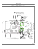
Page 168: ...Water Systems 9 8 FRESH WATER SYSTEM LAYOUT Figure 9 14 ...
Page 169: ...Water Systems 9 9 OPTIONAL AIR CONDITIONING PLUMBING LAYOUT Figure 9 15 ...
Page 170: ...Water Systems 9 10 OPTIONAL GENERATOR PLUMBING LAYOUT Figure 9 16 ...
Page 171: ...Water Systems 9 11 MANUAL TOILET RAW WATER HEAT EXCHANGER LAYOUTS Figure 9 17 ...
Page 172: ...Water Systems 9 12 Notes ...
Page 173: ...Waste Systems Chapter 10 MH37 MARLOW HUNTER LLC V1 R02_110714 ...
Page 174: ...Waste and Sanitation Systems This Page Intentionally Left Blank ...
Page 183: ...Waste and Sanitation Systems 10 9 BILGE SUMP PUMP DRAIN SYSTEM LAYOUT Figure 10 17 ...
Page 184: ...Waste and Sanitation Systems 10 10 AIR CONDITIONING WASTE WATER LAYOUT Figure 10 18 ...
Page 187: ...Waste and Sanitation Systems 10 13 Notes ...
Page 188: ...Waste and Sanitation Systems 10 14 Notes ...
Page 189: ...MH37 Engines Transmissions Chapter 11 MARLOW HUNTER LLC and V1 R02_110714 ...
Page 190: ...Engines and Transmissions This Page Intentionally Left Blank ...
Page 192: ...Engines and Transmissions 11 2 Engines and Transmissions 11 2 Figure 11 2 ...
Page 193: ...Engines and Transmissions 11 3 Figure 11 4 ...
Page 201: ...Engines and Transmissions 11 11 Notes ...
Page 202: ...Engines and Transmissions 11 12 Notes ...
Page 203: ...and MARLOW HUNTER LLC MH37 Sails Rigging Chapter 12 V1 R02_110714 ...
Page 204: ...Sails and Rigging This Page Intentionally Left Blank ...
Page 218: ...Sails and Rigging 12 14 Figure 12 14 GENERAL RIG COMPONENTS ...
Page 219: ...Sails and Rigging 12 15 MAINSAIL JIB SPECIFICATIONS Figure 12 15 ...
Page 220: ...Sails and Rigging 12 16 STANDING RIGGING SPECIFICATIONS STANDARD FURLING RIGS Figure 12 16 ...
Page 222: ...Sails and Rigging 12 18 Figure 12 18 RUNNING RIGGING SPECIFICATIONS ...
Page 224: ...Sails and Rigging 12 20 Figure 12 21 MAINSHEET BOOM OUTHAUL LAYOUT ...
Page 226: ...Sails and Rigging 12 22 VANG LAYOUT CONVENTIONAL SOLID Figure 12 23 ...
Page 228: ...Sails and Rigging 12 24 Figure 12 25 SPINNAKER LAYOUT OPTION ...
Page 229: ...Sails and Rigging 12 25 Figure 12 26 GENERALIZED REEFING LAYOUT ...
Page 230: ...Sails and Rigging 12 26 LAZY JACK LAYOUT WITH OPTIONAL STACK PACK SAIL COVER Figure 12 27 ...
Page 231: ...Sails and Rigging 12 27 STACK PACK SAIL COVER INSTALLATION WITH LAZY JACKS Figure 12 28 ...
Page 232: ...Sails and Rigging 12 28 Notes ...
Page 233: ...MH37 Getting Underway Chapter 13 MARLOW HUNTER LLC V1 R02_110714 ...
Page 234: ...Getting Underway This Page Intentionally Left Blank ...
Page 240: ...Getting Underway 13 6 Notes ...
Page 241: ...MH37 Maintenance Chapter 14 MARLOW HUNTER LLC V1 R02_110714 ...
Page 242: ...Maintenance This Page Intentionally Left Blank ...
Page 257: ...Maintenance 14 15 SLING LOCATIONS Figure 14 3 ...
Page 258: ...Maintenance 14 16 Notes ...
Page 259: ...Glossary Chapter 15 MH37 MARLOW HUNTER LLC V1 R02_110714 ...
Page 260: ...Glossary This Page Intentionally Left Blank ...


