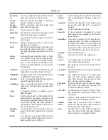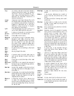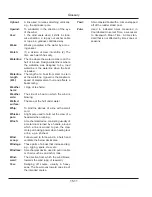
Glossary
15.3
Center
of effort
(COE):
The pont at whch all the forces actng on
the sals are concentrated.
Center
of lat-
eral resis-
tance
(CLR):
The underwater center of pressure about
whch a boat pvots when changng
course.
Center-
board:
A board lowered through a slot n the keel
to reduce leeway.
Chain
pawl:
A short lug whch drops nto a toothed
rack to prevent the anchor chan runnng
back.
Chain
plate:
A metal plate bolted to the boat to whch
the shrouds or backstays are attached.
Channel:
A navgable route on a waterway, usually
marked by buoys. Channels are smlar
to roads where the water s known to be
deep enough for shps or boats to sal
wthout runnng aground.
Chart
datum:
Reference level on a chart below whch
the tde s unlkely to fall. Soundngs are
gven below chart datum. The datum level
vares accordng to country and area.
Chart
table:
A table desgnated as the area n the boat
where the navgator wll study charts and
plot courses.
Chine:
The locaton where the deck jons the hull
of the boat.
Chop:
Small, steep dsorderly waves.
Cleat:
A wooden, metal or plastc fttng around
whch rope s secured.
Clevis
pin:
A lockng pn through whch a splt rng s
passed to prevent accdental wthdraw.
Clew:
The after, lower center of a sal where the
foot and leech meet.
Close
reach:
The pont of salng between close-hauled
and a beam reach, when the wnd blows
forward of the beam.
Close-
hauled:
The pont of salng closest to the wnd;
see also beat.
Close-
winded:
Descrbes a boat able to sal very close
to the wnd.
Coaming:
The rased structure surroundng a hatch,
cockpt, etc., whch prevents water enter-
ng.
Compass
course:
The course as read on a compass. The
compass course has added the magnetc
devaton and the magnetc varaton to
the true course.
Compass
rose:
A crcle on a chart ndcatng the drecton
of geographc north and sometmes also
magnetc north. Charts usually have more
that one compass rose. In that case the
compass rose nearest to the object beng
plotted should be used as the geographc
drectons and magnetc varatons may
change slghtly n dfferent places on the
chart.
Coordi-
nated
Univer-
sal Time
(UTC):
The nternatonal tme standard. It s the
current term for what was commonly
referred to as Greenwch Merdan Tme
(GMT). Zero (0) hours UTC s mdnght
n Greenwch England, whch les on the
zero longtudnal merdan. Unversal tme
s based on a 24 hour clock, therefore,
afternoon hours such as 4 p.m. UTC are
expressed as 16:00 UTC (sxteen hours,
zero mnutes). Snce a day s 24 hours
long, the world may be splt nto 15 degree
wde longtudnal bands (360 degrees/24
hours). Each band represents one hour.
As an example, Huntsvlle Alabama s
located at approxmately 90 degrees west
longtude, hence, local tme lags UTC
tme by 6 hours (90/15, assumng Central
Standard Tme, 5 hours n Central Daylght
Tme). So, f the unversal tme s 14:30
UTC, Unted States Central Standard
Tme would be 8:30 am CST. <http://www.
ghcc.msfc.nasa.gov/utc.html>
Cotter
pin:
Soft, metal pn folded back on tself to
form an eye.
Course:
The drecton n whch a vessel s steered,
usually gven n degrees; true, magnetc
or compass.
Cringle:
1, a rope loop, found at ether end of a lne
of reef ponts; 2, an eye n a sal.
Current:
The movement of water, due to tdes, rver
movement and crcular currents caused
by the moton of the earth.
Summary of Contents for MH37
Page 1: ...V1 R02_110714 Operator s Manual MH37 MARLOW HUNTER LLC ...
Page 2: ......
Page 11: ...Introduction Chapter 1 MH37 MARLOW HUNTER LLC V1 R02_110714 ...
Page 12: ...Introduction This Page Intentionally Left Blank ...
Page 17: ...Introduction 1 5 Notes ...
Page 18: ...Introduction 1 6 Notes ...
Page 19: ...Documents Forms Chapter 2 MH37 MARLOW HUNTER LLC and V1 R02_110714 ...
Page 20: ...Documents and Forms This Page Intentionally Left Blank ...
Page 44: ...Documents and Forms 2 24 Power Squadron recommendat ons for ma ntenance and safe boat ng ...
Page 46: ...Documents and Forms 2 26 Dates of pract ce dr lls and onboard safety nspect ons ...
Page 47: ...Documents and Forms My personal preferences for ma ntenance tems safety gear 2 27 ...
Page 48: ...Documents and Forms 2 28 Notes ...
Page 49: ...Limited Warranty Chapter 3 MH37 MARLOW HUNTER LLC V1 R02_110714 ...
Page 50: ...This Page Intentionally Left Blank Limited Warranty 3 2 ...
Page 64: ...Limited Warranty 3 16 Notes ...
Page 65: ...Boating Safety Chapter 4 MH37 MARLOW HUNTER LLC V1 R02_110714 ...
Page 66: ...Boating Safety This Page Intentionally Left Blank ...
Page 86: ...Boating Safety 4 20 DECK HARDWARE LAYOUT Figure 4 9 ...
Page 89: ...Boating Safety 4 23 Notes ...
Page 90: ...Boating Safety 4 24 Notes ...
Page 91: ...Fuel Systems Chapter 5 MH37 MARLOW HUNTER LLC V1 R02_110714 ...
Page 92: ...This Page Intentionally Left Blank Fuel Systems ...
Page 102: ...Figure 5 11 FUEL SYSTEM LAYOUT WITH OPTIONAL GENERATOR Fuel Systems 5 10 ...
Page 103: ...LPG SYSTEM LAYOUT Figure 5 12 Fuel Systems 5 11 ...
Page 104: ...Notes Fuel Systems 5 12 ...
Page 105: ...MH37 Underwater Gear Chapter 6 V1 R02_110714 MARLOW HUNTER LLC ...
Page 106: ...Underwater Gear This Page Intentionally Left Blank ...
Page 115: ...Underwater Gear 6 9 INTAKES DISCHARGES BELOW WATERLINE Figure 6 17 ...
Page 117: ...Underwater Gear 6 11 Notes ...
Page 118: ...Underwater Gear 6 12 Notes ...
Page 119: ...DC Electric System Chapter 7 MH37 MARLOW HUNTER LLC V1 R02_110714 ...
Page 120: ...DC Electric Systems This Page Intentionally Left Blank ...
Page 138: ...DC Electric Systems 7 18 DC OUTLET LAYOUT Figure 7 21 ...
Page 139: ...DC Electric Systems 7 19 Notes ...
Page 140: ...DC Electric Systems 7 20 Notes ...
Page 141: ...MARLOW HUNTER LLC MH37 AC Electric System Chapter 8 V1 R02_110714 ...
Page 142: ...AC Electric Systems This Page Intentionally Left Blank ...
Page 154: ...AC Electric Systems 8 12 AC SYSTEM MAJOR COMPONENT GENERAL LAYOUT WITH INVERTER Figure 8 17 ...
Page 156: ...AC Electric Systems 8 14 AIR CONDITIONER DUCTING LAYOUT Figure 8 19 ...
Page 157: ...AC Electric Systems 8 15 Notes ...
Page 158: ...AC Electric Systems 8 16 Notes ...
Page 159: ...MARLOW HUNTER LLC MH37 Water Systems Chapter 9 V1 R02_110714 ...
Page 160: ...Water Systems This Page Intentionally Left Blank ...
Page 168: ...Water Systems 9 8 FRESH WATER SYSTEM LAYOUT Figure 9 14 ...
Page 169: ...Water Systems 9 9 OPTIONAL AIR CONDITIONING PLUMBING LAYOUT Figure 9 15 ...
Page 170: ...Water Systems 9 10 OPTIONAL GENERATOR PLUMBING LAYOUT Figure 9 16 ...
Page 171: ...Water Systems 9 11 MANUAL TOILET RAW WATER HEAT EXCHANGER LAYOUTS Figure 9 17 ...
Page 172: ...Water Systems 9 12 Notes ...
Page 173: ...Waste Systems Chapter 10 MH37 MARLOW HUNTER LLC V1 R02_110714 ...
Page 174: ...Waste and Sanitation Systems This Page Intentionally Left Blank ...
Page 183: ...Waste and Sanitation Systems 10 9 BILGE SUMP PUMP DRAIN SYSTEM LAYOUT Figure 10 17 ...
Page 184: ...Waste and Sanitation Systems 10 10 AIR CONDITIONING WASTE WATER LAYOUT Figure 10 18 ...
Page 187: ...Waste and Sanitation Systems 10 13 Notes ...
Page 188: ...Waste and Sanitation Systems 10 14 Notes ...
Page 189: ...MH37 Engines Transmissions Chapter 11 MARLOW HUNTER LLC and V1 R02_110714 ...
Page 190: ...Engines and Transmissions This Page Intentionally Left Blank ...
Page 192: ...Engines and Transmissions 11 2 Engines and Transmissions 11 2 Figure 11 2 ...
Page 193: ...Engines and Transmissions 11 3 Figure 11 4 ...
Page 201: ...Engines and Transmissions 11 11 Notes ...
Page 202: ...Engines and Transmissions 11 12 Notes ...
Page 203: ...and MARLOW HUNTER LLC MH37 Sails Rigging Chapter 12 V1 R02_110714 ...
Page 204: ...Sails and Rigging This Page Intentionally Left Blank ...
Page 218: ...Sails and Rigging 12 14 Figure 12 14 GENERAL RIG COMPONENTS ...
Page 219: ...Sails and Rigging 12 15 MAINSAIL JIB SPECIFICATIONS Figure 12 15 ...
Page 220: ...Sails and Rigging 12 16 STANDING RIGGING SPECIFICATIONS STANDARD FURLING RIGS Figure 12 16 ...
Page 222: ...Sails and Rigging 12 18 Figure 12 18 RUNNING RIGGING SPECIFICATIONS ...
Page 224: ...Sails and Rigging 12 20 Figure 12 21 MAINSHEET BOOM OUTHAUL LAYOUT ...
Page 226: ...Sails and Rigging 12 22 VANG LAYOUT CONVENTIONAL SOLID Figure 12 23 ...
Page 228: ...Sails and Rigging 12 24 Figure 12 25 SPINNAKER LAYOUT OPTION ...
Page 229: ...Sails and Rigging 12 25 Figure 12 26 GENERALIZED REEFING LAYOUT ...
Page 230: ...Sails and Rigging 12 26 LAZY JACK LAYOUT WITH OPTIONAL STACK PACK SAIL COVER Figure 12 27 ...
Page 231: ...Sails and Rigging 12 27 STACK PACK SAIL COVER INSTALLATION WITH LAZY JACKS Figure 12 28 ...
Page 232: ...Sails and Rigging 12 28 Notes ...
Page 233: ...MH37 Getting Underway Chapter 13 MARLOW HUNTER LLC V1 R02_110714 ...
Page 234: ...Getting Underway This Page Intentionally Left Blank ...
Page 240: ...Getting Underway 13 6 Notes ...
Page 241: ...MH37 Maintenance Chapter 14 MARLOW HUNTER LLC V1 R02_110714 ...
Page 242: ...Maintenance This Page Intentionally Left Blank ...
Page 257: ...Maintenance 14 15 SLING LOCATIONS Figure 14 3 ...
Page 258: ...Maintenance 14 16 Notes ...
Page 259: ...Glossary Chapter 15 MH37 MARLOW HUNTER LLC V1 R02_110714 ...
Page 260: ...Glossary This Page Intentionally Left Blank ...


