41866-01 02/20/2004
© 2004 Hunter Fan Company
10
10
10
10
10
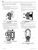
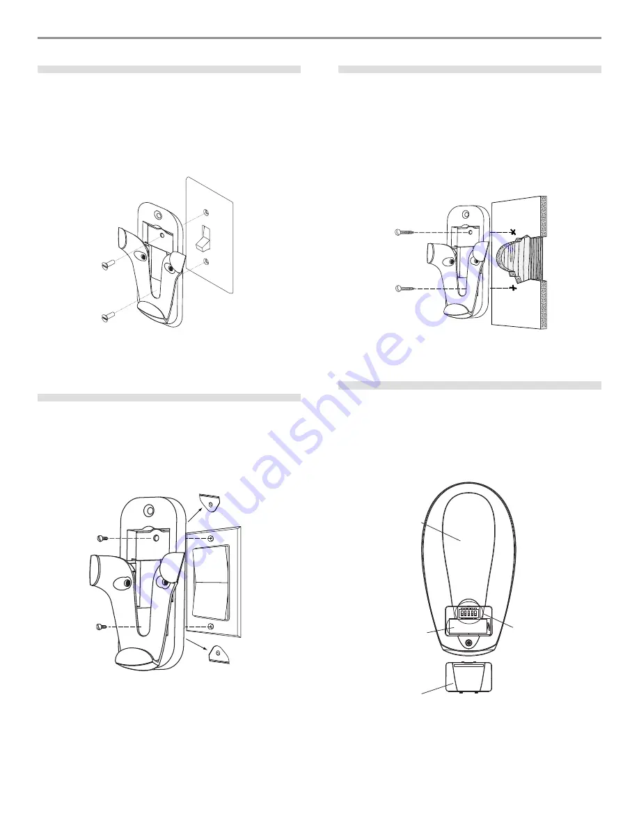
installing the remote cradle on a standard light
switch
1.
Remove the two screws holding the switch cover plate. Do
not remove the cover plate.
2.
Orient the control cradle as shown in Figure 31, and line up
the two inner mounting holes with those on the switch, insert
screws, don't over tighten.
FFFFFiiiiigggggur
ur
ur
ur
ure 31 - I
e 31 - I
e 31 - I
e 31 - I
e 31 - Innnnnssssstttttaaaaallin
llin
llin
llin
lling t
g t
g t
g t
g thhhhhe r
e r
e r
e r
e reeeeem
m
m
m
mooooottttte c
e c
e c
e c
e crrrrraaaaadddddllllle o
e o
e o
e o
e on a s
n a s
n a s
n a s
n a stttttaaaaannnnndddddaaaaarrrrrd li
d li
d li
d li
d liggggghhhhhttttt
sssssw
w
w
w
wiiiiitttttccccchhhhh
3.
Continue to in
in
in
in
inssssstttttaaaaallin
llin
llin
llin
lling t
g t
g t
g t
g thhhhhe b
e b
e b
e b
e baaaaatttttttttteeeeerrrrryyyyy.
installing the remote cradle on a rocker light switch
1.
Break off the two tabs by pushing outward. See Figure 32.
2.
Remove the two screws holding the switch cover plate. Do not
remove the cover plate.
3.
Orient the remote cradle as shown in Figure 32. Line up the
two outer mounting holes with those on the switch , insert
screws, don't over tighten.
FFFFFiiiiigggggur
ur
ur
ur
ure 32 - I
e 32 - I
e 32 - I
e 32 - I
e 32 - Innnnnssssstttttaaaaallin
llin
llin
llin
lling t
g t
g t
g t
g thhhhhe r
e r
e r
e r
e reeeeem
m
m
m
mooooottttte c
e c
e c
e c
e crrrrraaaaadddddllllle o
e o
e o
e o
e on a r
n a r
n a r
n a r
n a roooooccccckkkkkeeeeer li
r li
r li
r li
r liggggghhhhhttttt
sssssw
w
w
w
wiiiiitttttccccchhhhh
4.
Continue to in
in
in
in
inssssstttttaaaaallin
llin
llin
llin
lling t
g t
g t
g t
g thhhhhe b
e b
e b
e b
e baaaaatttttttttteeeeerrrrryyyyy.
installing the remote cradle on the wall
1.
Locate a 2 x 4 wall stud in a convenient location.
2.
Orient the remote cradle as shown in Figure 33, over the 2x4
stud.
3.
Use the 1" wood screws in either the inner or outer mounting
holes.
NOTE: Wall anchors and 6-32 x 1" screws may be used in situ-
ations where mounting to a stud is not possible. Use the inner
mounting holes.
FFFFFiiiiigggggur
ur
ur
ur
ure 33 - I
e 33 - I
e 33 - I
e 33 - I
e 33 - Innnnnssssstttttaaaaallin
llin
llin
llin
lling t
g t
g t
g t
g thhhhhe r
e r
e r
e r
e reeeeem
m
m
m
mooooottttte c
e c
e c
e c
e crrrrraaaaadddddllllle o
e o
e o
e o
e on t
n t
n t
n t
n thhhhhe w
e w
e w
e w
e waaaaallllllllll
4.
Continue to in
in
in
in
inssssstttttaaaaallin
llin
llin
llin
lling t
g t
g t
g t
g thhhhhe b
e b
e b
e b
e baaaaatttttttttteeeeerrrrryyyyy.
installing the battery
1.
Remove the cover off the back of the remote as shown in
Figure 34.
2.
Install the included 12 volt alkaline battery (Type 23A, MN-21
or equivalent) inside the remote, matching polarity on the Bat-
tery as indicated by the + and - symbols in the Battery Com-
partment. See Figure 34. Replace the cover.
FFFFFiiiiigggggur
ur
ur
ur
ure 34 - I
e 34 - I
e 34 - I
e 34 - I
e 34 - Innnnnssssstttttaaaaallin
llin
llin
llin
lling t
g t
g t
g t
g thhhhhe b
e b
e b
e b
e baaaaatttttttttteeeeerrrrry a
y a
y a
y a
y annnnnd s
d s
d s
d s
d seeeeettttttttttin
in
in
in
ing t
g t
g t
g t
g thhhhhe dip
e dip
e dip
e dip
e dip
sssssw
w
w
w
wiiiiitttttccccchhhhheeeeesssss
Back of Remote
Dip Switches
Battery
Compartment
Cover

