background image

418

66

-01  0

2

/

20

/200

© 200

4

 Hunter Fan Company

6

66

6

6

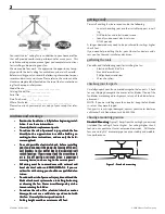
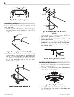
installing the adapter cover

1.

Using the three #6-32 x 

3

/

8

” screws, align the holes in the

adapter cover with the holes in the top housing.  Refer to Fig-
ure 14.

2.

Tighten the three screws.

F

FF

FFiiiiig

gg

ggur

ur

ur

ur

ure 14 - I

e 14 - I

e 14 - I

e 14 - I

e 14 - In

n

n

n

nsssssttttta

aa

aallin

llin

llin

llin

lling t

g t

g t

g t

g th

h

h

h

he a

e a

e a

e a

e ad

d

d

d

da

aa

aap

p

p

p

pttttte

ee

eer c

r c

r c

r c

r co

o

o

o

ov

vv

vveeeeerrrrr

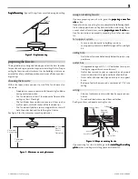
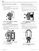
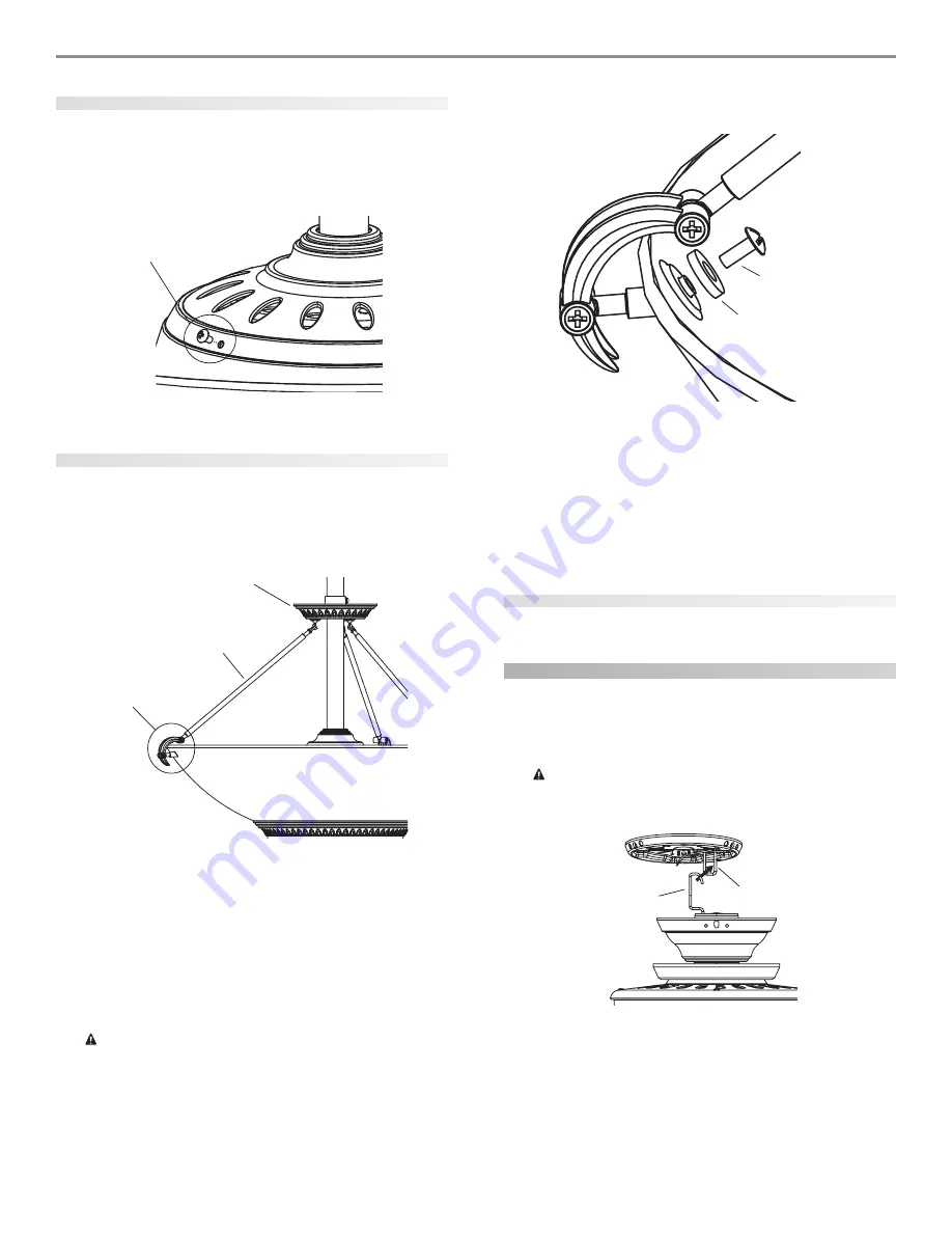
installing the decorative arms

1.

Hook one arm onto the arm mounting ring as shown in Figure
15.

2.

Slide the ring up the downrod until the hook assembly on the
arm fits correctly in the alabaster bowl.  Refer to Figure 15.

F

FF

FFiiiiig

gg

ggur

ur

ur

ur

ure 15 - D

e 15 - D

e 15 - D

e 15 - D

e 15 - De

ee

eettttteeeeerrrrrm

m

m

m

min

in

in

in

inin

in

in

in

ing t

g t

g t

g t

g th

h

h

h

he p

e p

e p

e p

e pllllla

aa

aaccccceeeeem

m

m

m

me

ee

een

n

n

n

nt f

t f

t f

t f

t fo

o

o

o

or t

r t

r t

r t

r th

h

h

h

he a

e a

e a

e a

e arrrrrm

m

m

m

m

m

m

m

m

mo

o

o

o

oun

un

un

un

untttttin

in

in

in

ing r

g r

g r

g r

g rin

in

in

in

ing

gg

gg

3.

Using the included allen wrench, tighten the allen head set
screw on the arm mounting ring just enough to keep it from
moving.
NOTE:  After all three arms are completely assembled, you will
securely tighten the set screw.  While assembling the arms, you
may have to loosen the set screw to move the arm mounting
ring up or down.

C

C

C

C

CA

A

A

A

AU

U

U

U

UT

T

T

T

TIIIIIO

O

O

O

ON:  D

N:  D

N:  D

N:  D

N:  Do n

o n

o n

o n

o no

o

o

o

ot a

t a

t a

t a

t all

ll

ll

ll

llo

o

o

o

ow t

w t

w t

w t

w th

h

h

h

he a

e a

e a

e a

e arrrrrm m

m m

m m

m m

m mo

o

o

o

oun

un

un

un

untttttin

in

in

in

ing r

g r

g r

g r

g rin

in

in

in

ing t

g t

g t

g t

g to t

o t

o t

o t

o tw

w

w

w

wiiiiisssssttttt

a

aa

aafffffttttteeeeer b

r b

r b

r b

r be

ee

eeg

gg

gginn

inn

inn

inn

innin

in

in

in

ing t

g t

g t

g t

g th

h

h

h

he a

e a

e a

e a

e arrrrrm a

m a

m a

m a

m asssssssssse

ee

eemb

mb

mb

mb

mblllllyyyyy.  T

.  T

.  T

.  T

.  Tw

w

w

w

wiiiiissssstttttin

in

in

in

ing m

g m

g m

g m

g ma

aa

aay c

y c

y c

y c

y ca

aa

aau

u

u

u

ussssse a

e a

e a

e a

e a

h

h

h

h

ho

o

o

o

oo

o

o

o

ok t

k t

k t

k t

k to b

o b

o b

o b

o brrrrre

ee

eeaaaaak o

k o

k o

k o

k offffff o

f o

f o

f o

f of t

f t

f t

f t

f th

h

h

h

he a

e a

e a

e a

e arrrrrm m

m m

m m

m m

m mo

o

o

o

oun

un

un

un

untttttin

in

in

in

ing r

g r

g r

g r

g rin

in

in

in

ing

gg

gg.....

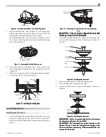
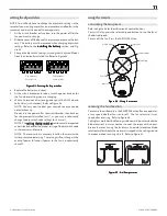
4.

Assemble the nylon washer and #6-32 x 3/8” screw onto the
end of the arm hook assembly as shown in Figure 16.

F

FF

FFiiiiig

gg

ggur

ur

ur

ur

ure 16 - I

e 16 - I

e 16 - I

e 16 - I

e 16 - In

n

n

n

nsssssttttta

aa

aallin

llin

llin

llin

lling t

g t

g t

g t

g th

h

h

h

he a

e a

e a

e a

e arrrrrm

m

m

m

m

5.

Repeat steps 1 through 4, but skip steps 2 and 3 if it is not
necessary to move the arm mounting ring to assemble the next
arm.

6.

Tighten the two screws on each arm hook assembly as shown
in Figure 16.

7.

Securely tighten the allen head set screw on the arm mount-
ing ring.

installing the light bulbs

Install 4 B10, 40 Watt Max bulbs.

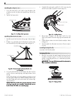
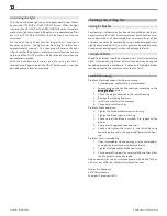
hanging the fan

1.

Raise the fan and place the hook through the loop on the ceil-
ing plate as shown in Figure 17.  Use the note and arrow en-
graved in the ceiling plate to assist in determining the direc-
tion to assemble.

W

W

W

W

WA

A

A

A

AR

R

R

R

RN

N

N

N

NIIIIIN

N

N

N

NG:  F

G:  F

G:  F

G:  F

G:  Fa

aa

aan m

n m

n m

n m

n ma

aa

aay f

y f

y f

y f

y fa

aa

aall i

ll i

ll i

ll i

ll if n

f n

f n

f n

f no

o

o

o

ot a

t a

t a

t a

t asssssssssse

ee

eemb

mb

mb

mb

mbllllle

ee

eed a

d a

d a

d a

d as dir

s dir

s dir

s dir

s dire

ee

eecccccttttteeeeed in

d in

d in

d in

d in

ttttth

h

h

h

he

ee

eessssse in

e in

e in

e in

e insssssttttta

aa

aall

ll

ll

ll

lla

aa

aatttttiiiiio

o

o

o

on in

n in

n in

n in

n inssssstttttrrrrru

u

u

u

uccccctttttiiiiio

o

o

o

on

n

n

n

nsssss.....

F

FF

FFiiiiig

gg

ggur

ur

ur

ur

ure 17 - Ha

e 17 - Ha

e 17 - Ha

e 17 - Ha

e 17 - Han

n

n

n

ng

gg

ggin

in

in

in

ing t

g t

g t

g t

g th

h

h

h

he f

e f

e f

e f

e fa

aa

aan

n

n

n

n

#6-32 x 

3

/

8

” screw

Arm Mounting Ring

Arm

Hook Assembly

#6-32 x 3/8” Screw

Nylon Washer

Hook

Loop

Summary of Contents for State Street

Page 1: ... 2004 Hunter Fan Company 41864 01 02 19 2004 1 41866 01 02 20 2004 ...

Page 2: ... ne e e e el l l l l A A A A All w ll w ll w ll w ll wir ir ir ir irin in in in ing mu g mu g mu g mu g mus s s s st b t b t b t b t be in a e in a e in a e in a e in ac c c c cc c c c co o o o or r r r rd d d d da a a a an n n n nc c c c ce w e w e w e w e wi ii i it t t t th n h n h n h n h na a a a at t t t ti ii i io o o o on n n n na a a a al a l a l a l a l an n n n nd d d d d l ll l lo o o ...

Page 3: ...t t t t te e e e e section If you plan to use an existing fan site complete the following check list for the support brace ceiling hole outlet box and wiring If you cannot check off every item see the p p p p pr r r r re e e e ep p p p pa a a a ar r r r rin in in in ing a n g a n g a n g a n g a ne e e e ew f w f w f w f w fa a a a an si n si n si n si n sit t t t te e e e e sec tion for instructi...

Page 4: ...da a a a an n n n nc c c c ce w e w e w e w e wi ii i it t t t th n h n h n h n h na a a a a t t t t ti ii i io o o o on n n n na a a a al a l a l a l a l an n n n nd l d l d l d l d lo o o o oc c c c ca a a a al e l e l e l e l el ll l le e e e ec c c c ct t t t tr r r r ri ii i ic c c c ca a a a al c l c l c l c l co o o o od d d d de e e e es a s a s a s a s an n n n nd A d A d A d A d AN N N N...

Page 5: ... e do o o o ow w w w wnr nr nr nr nro o o o od d d d d 2 Insert the downrod through the canopy the canopy trim ring the arm mounting ring and the adapter cover as shown in Figure 12 F F F F Fi ii i ig g g g gur ur ur ur ure 12 I e 12 I e 12 I e 12 I e 12 In n n n ns s s s st t t t ta a a a allin llin llin llin lling t g t g t g t g th h h h he d e d e d e d e do o o o ow w w w wnr nr nr nr nro o o...

Page 6: ... as s s s ss s s s se e e e emb mb mb mb mbl ll l ly y y y y T T T T Tw w w w wi ii i is s s s st t t t tin in in in ing m g m g m g m g ma a a a ay c y c y c y c y ca a a a au u u u us s s s se a e a e a e a e a h h h h ho o o o oo o o o ok t k t k t k t k to b o b o b o b o br r r r re e e e ea a a a ak o k o k o k o k of f f f ff o f o f o f o f of t f t f t f t f th h h h he a e a e a e a e ar...

Page 7: ... ll l le e e e ec c c c ct t t t tr r r r ri ii i ic c c c ci ii i ia a a a an n n n n F F F F Fi ii i ig g g g gur ur ur ur ure 18 W e 18 W e 18 W e 18 W e 18 Wir ir ir ir irin in in in ing t g t g t g t g th h h h he f e f e f e f e fa a a a an n n n n installing the canopy 1 Rotate the fan 180º clockwise from the initial position when hanging the fan The arrows on the hanger ball and on the cei...

Page 8: ...5 A e 25 A e 25 A e 25 At t t t tt t t t ta a a a ac c c c ch h h h hin in in in ing t g t g t g t g th h h h he b e b e b e b e bl ll l la a a a ad d d d de t e t e t e t e to t o t o t o t o th h h h he b e b e b e b e bl ll l la a a a ad d d d de ir e ir e ir e ir e iro o o o on a n a n a n a n an n n n nd d d d d m m m m me e e e ed d d d da a a a alli lli lli lli llio o o o on n n n n If you ...

Page 9: ...ta a a a allin llin llin llin lling w g w g w g w g wi ii i it t t t th h h h ho o o o ou u u u ut t t t t t t t t th h h h he li e li e li e li e lig g g g gh h h h ht f t f t f t f t fi ii i ix x x x xt t t t tur ur ur ur ure e e e e setting up the remote F F F F FC C C C CC I C I C I C I C In n n n nf f f f fo o o o or r r r rm m m m ma a a a at t t t ti ii i io o o o on n n n n 1 This device c...

Page 10: ...t t t s s s s sw w w w wi ii i it t t t tc c c c ch h h h h 4 Continue to in in in in ins s s s st t t t ta a a a allin llin llin llin lling t g t g t g t g th h h h he b e b e b e b e ba a a a at t t t tt t t t te e e e er r r r ry y y y y installing the remote cradle on the wall 1 Locate a 2 x 4 wall stud in a convenient location 2 Orient the remote cradle as shown in Figure 33 over the 2x4 stud...

Page 11: ...s well NOTE The s s s s se e e e et t t t tt t t t tin in in in ing t g t g t g t g th h h h he dip s e dip s e dip s e dip s e dip sw w w w wi ii i it t t t tc c c c ch h h h he e e e es s s s s section mustberepeated asdescribedaboveforthepropersettingofthedipswitchcode in the receiver and remote NOTE The receiver has a memory function that retains the last dip switch code setting The setting wi...

Page 12: ...s until snug 3 Check to see if the blade is cracked If so replace all the blades 4 Change to an approved speed control 5 Check and tighten the screws in the switch housing mounting plate and in the upper and lower switch hous ing Problem Excessive wobbling 1 If your fan wobbles when operating use the enclosed bal ancing kit and instructions to balance the fan 2 Tighten all blade and or blade iron ...

Reviews: