background image

© 200

4

 Hunter Fan Company

418

66

-01  0

2

/

20

/200

4

7

77

7

7

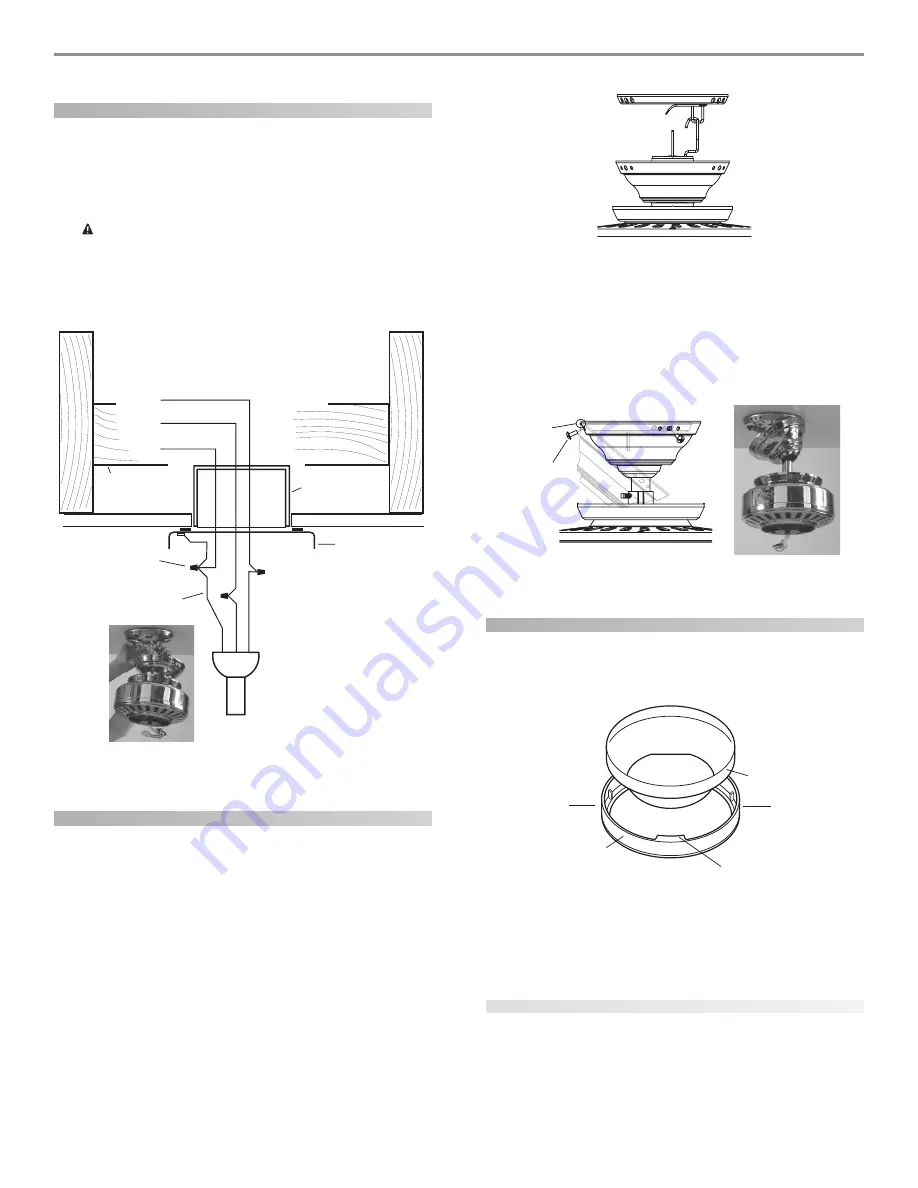
wiring the fan

1.

Disconnect the power by turning off the circuit breakers to
the outlet box and associated wall switch location.

2.

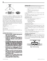
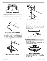
Connect the wires as shown in Figure 18. To connect the wires,
twist the bare metal leads together. Place a wire nut over the
intertwined length of wire and twist clockwise until tight as.

C

C

C

C

CA

A

A

A

AU

U

U

U

UT

T

T

T

TIIIIIO

O

O

O

ON:  B

N:  B

N:  B

N:  B

N:  Be s

e s

e s

e s

e sur

ur

ur

ur

ure n

e n

e n

e n

e no b

o b

o b

o b

o ba

aa

aarrrrre w

e w

e w

e w

e wir

ir

ir

ir

ire o

e o

e o

e o

e or w

r w

r w

r w

r wir

ir

ir

ir

ire s

e s

e s

e s

e stttttrrrrra

aa

aan

n

n

n

nd

d

d

d

ds a

s a

s a

s a

s arrrrre v

e v

e v

e v

e viiiiisssss-----

ib

ib

ib

ib

ibllllle a

e a

e a

e a

e afffffttttte

ee

eer m

r m

r m

r m

r ma

aa

aak

kk

kkin

in

in

in

ing c

g c

g c

g c

g co

o

o

o

onn

nn

nn

nn

nne

ee

eeccccctttttiiiiio

o

o

o

on

n

n

n

nsssss.....

A

A

A

A

All w

ll w

ll w

ll w

ll wir

ir

ir

ir

irin

in

in

in

ing mu

g mu

g mu

g mu

g mussssst b

t b

t b

t b

t be in a

e in a

e in a

e in a

e in acccccccccco

o

o

o

orrrrrd

d

d

d

da

aa

aan

n

n

n

nccccce w

e w

e w

e w

e wiiiiittttth n

h n

h n

h n

h na

aa

aatttttiiiiio

o

o

o

on

n

n

n

na

aa

aal a

l a

l a

l a

l an

n

n

n

nd l

d l

d l

d l

d lo

o

o

o

occccca

aa

aalllll

e

ee

eellllleeeeeccccctttttrrrrriiiiicccccaaaaal c

l c

l c

l c

l co

o

o

o

od

d

d

d

de

ee

ees a

s a

s a

s a

s an

n

n

n

nd A

d A

d A

d A

d AN

N

N

N

NS

SS

SSI/N

I/N

I/N

I/N

I/NF

FF

FFP

P

P

P

PA 70. I

A 70. I

A 70. I

A 70. I

A 70. If y

f y

f y

f y

f yo

o

o

o

ou a

u a

u a

u a

u arrrrre un

e un

e un

e un

e unfffffa

aa

aam

m

m

m

mili

ili

ili

ili

ilia

aa

aarrrrr

w

w

w

w

wiiiiittttth w

h w

h w

h w

h wir

ir

ir

ir

irin

in

in

in

ing

gg

gg, y

, y

, y

, y

, yo

o

o

o

ou s

u s

u s

u s

u sh

h

h

h

ho

o

o

o

oul

ul

ul

ul

uld u

d u

d u

d u

d ussssse a q

e a q

e a q

e a q

e a qu

u

u

u

ua

aa

aali

li

li

li

lifffffiiiiie

ee

eed e

d e

d e

d e

d ellllle

ee

eeccccctttttrrrrriiiiiccccciiiiiaaaaan

n

n

n

n.....

F

FF

FFiiiiig

gg

ggur

ur

ur

ur

ure 18 - W

e 18 - W

e 18 - W

e 18 - W

e 18 - Wir

ir

ir

ir

irin

in

in

in

ing t

g t

g t

g t

g th

h

h

h

he f

e f

e f

e f

e fa

aa

aan

n

n

n

n

installing the canopy

1.

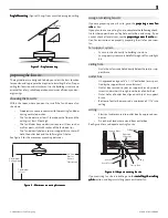
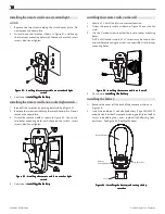
Rotate the fan 180º clockwise from the initial position when
hanging the fan.  The arrows on the hanger ball and on the
ceiling plate should be pointing in the same direction and
should be pointing towards the tab hole on the canopy.  Refer
to Figure 19.

F

FF

FFiiiiig

gg

ggur

ur

ur

ur

ure 19 - R

e 19 - R

e 19 - R

e 19 - R

e 19 - Ro

o

o

o

ottttta

aa

aatttttin

in

in

in

ing t

g t

g t

g t

g th

h

h

h

he f

e f

e f

e f

e fa

aa

aan

n

n

n

n

2.

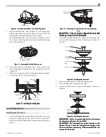
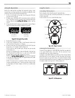
Hook the tab hole over the tab on the ceiling plate as shown in
Figure 20.

3.

Raise the canopy, be sure the holes in the canopy and the ceil-
ing plate are aligned, and loosely assemble the canopy screws
one at a time.  When all three screws are assembled, securely
tighten all three canopy screws.  Refer to Figure 20.

F

FF

FFiiiiig

gg

ggur

ur

ur

ur

ure 20 - I

e 20 - I

e 20 - I

e 20 - I

e 20 - In

n

n

n

nsssssttttta

aa

aallin

llin

llin

llin

lling t

g t

g t

g t

g th

h

h

h

he c

e c

e c

e c

e ca

aa

aan

n

n

n

no

o

o

o

op

p

p

p

pyyyyy

installing the canopy trim ring

1.

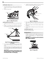
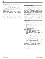
To easily install the canopy trim ring, locate the two tabs on
the canopy trim ring.  See Figure 21.

F

FF

FFiiiiig

gg

ggur

ur

ur

ur

ure 21 - C

e 21 - C

e 21 - C

e 21 - C

e 21 - Ca

aa

aan

n

n

n

no

o

o

o

op

p

p

p

py t

y t

y t

y t

y trrrrrim r

im r

im r

im r

im rin

in

in

in

ing

gg

gg

2.

Take both hands and push the canopy trim ring up to the top
of the canopy.  See Figure 21.

3.

The canopy trim ring will snap and lock into place on the
canopy.

removing the canopy trim ring

1.

Locate the tab indicators, small bumps on top of tabs.  Refer to
Figure 22.

2.

To remove the canopy trim ring, press firmly on opposite sides
of the ring towards the canopy as shown in Figure 22.  The tabs
will flex out releasing the trim ring from the canopy.

Tab Hole
and Tab

Canopy
Screw

Power
Wires
in
Ceiling

Black

White

Bare or Green

2 x 4 Brace

Outlet Box

Ceiling Plate

Approved
Connectors

Green Ground Wire from
Hanger Pipe

Wh

it

e

Bl

a

ck

Canopy

Canopy
Trim Ring

Tab

Press Here when
Removing

Press Here when
Removing

Summary of Contents for State Street

Page 1: ... 2004 Hunter Fan Company 41864 01 02 19 2004 1 41866 01 02 20 2004 ...

Page 2: ... ne e e e el l l l l A A A A All w ll w ll w ll w ll wir ir ir ir irin in in in ing mu g mu g mu g mu g mus s s s st b t b t b t b t be in a e in a e in a e in a e in ac c c c cc c c c co o o o or r r r rd d d d da a a a an n n n nc c c c ce w e w e w e w e wi ii i it t t t th n h n h n h n h na a a a at t t t ti ii i io o o o on n n n na a a a al a l a l a l a l an n n n nd d d d d l ll l lo o o ...

Page 3: ...t t t t te e e e e section If you plan to use an existing fan site complete the following check list for the support brace ceiling hole outlet box and wiring If you cannot check off every item see the p p p p pr r r r re e e e ep p p p pa a a a ar r r r rin in in in ing a n g a n g a n g a n g a ne e e e ew f w f w f w f w fa a a a an si n si n si n si n sit t t t te e e e e sec tion for instructi...

Page 4: ...da a a a an n n n nc c c c ce w e w e w e w e wi ii i it t t t th n h n h n h n h na a a a a t t t t ti ii i io o o o on n n n na a a a al a l a l a l a l an n n n nd l d l d l d l d lo o o o oc c c c ca a a a al e l e l e l e l el ll l le e e e ec c c c ct t t t tr r r r ri ii i ic c c c ca a a a al c l c l c l c l co o o o od d d d de e e e es a s a s a s a s an n n n nd A d A d A d A d AN N N N...

Page 5: ... e do o o o ow w w w wnr nr nr nr nro o o o od d d d d 2 Insert the downrod through the canopy the canopy trim ring the arm mounting ring and the adapter cover as shown in Figure 12 F F F F Fi ii i ig g g g gur ur ur ur ure 12 I e 12 I e 12 I e 12 I e 12 In n n n ns s s s st t t t ta a a a allin llin llin llin lling t g t g t g t g th h h h he d e d e d e d e do o o o ow w w w wnr nr nr nr nro o o...

Page 6: ... as s s s ss s s s se e e e emb mb mb mb mbl ll l ly y y y y T T T T Tw w w w wi ii i is s s s st t t t tin in in in ing m g m g m g m g ma a a a ay c y c y c y c y ca a a a au u u u us s s s se a e a e a e a e a h h h h ho o o o oo o o o ok t k t k t k t k to b o b o b o b o br r r r re e e e ea a a a ak o k o k o k o k of f f f ff o f o f o f o f of t f t f t f t f th h h h he a e a e a e a e ar...

Page 7: ... ll l le e e e ec c c c ct t t t tr r r r ri ii i ic c c c ci ii i ia a a a an n n n n F F F F Fi ii i ig g g g gur ur ur ur ure 18 W e 18 W e 18 W e 18 W e 18 Wir ir ir ir irin in in in ing t g t g t g t g th h h h he f e f e f e f e fa a a a an n n n n installing the canopy 1 Rotate the fan 180º clockwise from the initial position when hanging the fan The arrows on the hanger ball and on the cei...

Page 8: ...5 A e 25 A e 25 A e 25 At t t t tt t t t ta a a a ac c c c ch h h h hin in in in ing t g t g t g t g th h h h he b e b e b e b e bl ll l la a a a ad d d d de t e t e t e t e to t o t o t o t o th h h h he b e b e b e b e bl ll l la a a a ad d d d de ir e ir e ir e ir e iro o o o on a n a n a n a n an n n n nd d d d d m m m m me e e e ed d d d da a a a alli lli lli lli llio o o o on n n n n If you ...

Page 9: ...ta a a a allin llin llin llin lling w g w g w g w g wi ii i it t t t th h h h ho o o o ou u u u ut t t t t t t t t th h h h he li e li e li e li e lig g g g gh h h h ht f t f t f t f t fi ii i ix x x x xt t t t tur ur ur ur ure e e e e setting up the remote F F F F FC C C C CC I C I C I C I C In n n n nf f f f fo o o o or r r r rm m m m ma a a a at t t t ti ii i io o o o on n n n n 1 This device c...

Page 10: ...t t t s s s s sw w w w wi ii i it t t t tc c c c ch h h h h 4 Continue to in in in in ins s s s st t t t ta a a a allin llin llin llin lling t g t g t g t g th h h h he b e b e b e b e ba a a a at t t t tt t t t te e e e er r r r ry y y y y installing the remote cradle on the wall 1 Locate a 2 x 4 wall stud in a convenient location 2 Orient the remote cradle as shown in Figure 33 over the 2x4 stud...

Page 11: ...s well NOTE The s s s s se e e e et t t t tt t t t tin in in in ing t g t g t g t g th h h h he dip s e dip s e dip s e dip s e dip sw w w w wi ii i it t t t tc c c c ch h h h he e e e es s s s s section mustberepeated asdescribedaboveforthepropersettingofthedipswitchcode in the receiver and remote NOTE The receiver has a memory function that retains the last dip switch code setting The setting wi...

Page 12: ...s until snug 3 Check to see if the blade is cracked If so replace all the blades 4 Change to an approved speed control 5 Check and tighten the screws in the switch housing mounting plate and in the upper and lower switch hous ing Problem Excessive wobbling 1 If your fan wobbles when operating use the enclosed bal ancing kit and instructions to balance the fan 2 Tighten all blade and or blade iron ...

Reviews: