background image


••••

 Getting Started 

TC39 Series Changer Operation Instructions 

IMPORTANT SAFETY INSTRUCTIONS 

 WARNING:  This machine stores and uses significant volumes of compressed air. 

Disconnect compressed air at the source and drain all compressed air 
before servicing. Severe injury or death can occur if service is 
attempted on a compressed air chamber while it is charged. 


 WARNING:  This machine uses high voltage electrical power. Shut down and 

unplug the machine at the source before servicing. Severe injury or 
death can occur if service is attempted on a live electrical circuit. 

Read and follow all caution and warning labels affixed to equipment and tools. 

Read and understand all instructions before operating this machine. 

Misuse of this equipment can cause personal injury and shorten the life of the TC. 

To prevent accidents or damage to the TC, use only Hunter recommended procedures and 
accessories. 

Wear OSHA approved eye protection while operating the TC. 

Wear non-slip safety footwear when operating the TC. 

Do not wear jewelry or loose clothing when operating the TC. 

Wear proper back support when lifting or removing wheel from the TC. 

Never stand on the TC. 
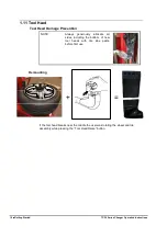
 WARNING: 

Keep hands and clothing clear of moving parts. Keep hands clear 
of upper roller when bead loosening or rotating clamped wheel. 
Do not lean or reach over tire when inflating. 


 WARNING: 

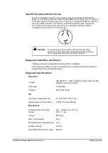
Do not exceed these pressure limitations: 


SUPPLY LINE PRESSURE (from compressor) 175 PSI. 


OPERATING PRESSURE (gauge on regulator) 145 PSI. 


BEAD SEATING PRESSURE (gauge on hose) 40 PSI. 


 WARNING: 

Never mount a tire to a rim that is not the same diameter (e.g., 16 
1/2 inch tire mounting on a 16 inch rim). 


 WARNING: 

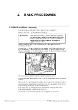
After loss of air line pressure ALWAYS raise the wheel lift pedal 
to prevent the wheel lift from rising quickly during first operation. 


 DANGER: 

Activate blast inflation nozzle only when seating bead. 


 CAUTION: 

Do not hose down or power wash electric tire changers. 

Bleed air pressure from system before disconnecting supply line or other pneumatic 
components. Air is stored in a reservoir for operation of the blast inflation nozzle. Air 
pressure can be bled from the system by pulling up on the knob located on top of the 
regulator, and then turning it counterclockwise

Do not activate the blast inflation nozzle if the tire is not properly clamped. 

Summary of Contents for TC39 Series

Page 1: ... Copyright 2018 Hunter Engineering Company OPERATION INSTRUCTIONS 7108 M010 3_H Rev 3 02 2020 TC39 Series Tire Changer ...

Page 2: ...one Number_____________________________________________________________________ Concept and Procedure Explanation Safety Precautions Trained Declined Warning and Caution Labels Bead Roller Maintenance and Performance Checks Trained Declined Air Pressure Check Checking Arm Calibration to Rims Adjustment and Filling of Oiler Wheel Clamping Trained Declined Drop Center Identification Standard Wheel R...

Page 3: ..._______ ___________________________________ ___________________________________ ___________________________________ ___________________________________ ___________________________________ ___________________________________ ___________________________________ ___________________________________ ___________________________________ ___________________________________ ________________________________...

Page 4: ...rm 7 1 9 Command unit 7 1 10 Equipment Components 9 1 11 Tool Head 10 Tool Head Damage Prevention 10 2 BASIC PROCEDURES 12 2 1 Side Shovel Bead Loosening 12 2 2 Placing Wheel on TC 13 Wheel Support Plate Height Adjustment 13 Standard and High Offset Wheels 14 Reverse Drop Center Wheels 15 Large Pilot Hole Wheels 17 2 3 Bead Loosening 18 2 4 Demounting Tires from Rim 19 2 5 Mounting Tire to Rim 21 ...

Page 5: ... procedures and maintenance Italics are used to refer to specific parts of this manual that provide additional information or explanation For example refer to Equipment Components page 9 These references should be read for additional information to the instructions being presented The owner of the TC is solely responsible for arranging technical training The TC is to be operated only by a qualifie...

Page 6: ...when operating the TC Wear proper back support when lifting or removing wheel from the TC Never stand on the TC WARNING Keep hands and clothing clear of moving parts Keep hands clear of upper roller when bead loosening or rotating clamped wheel Do not lean or reach over tire when inflating WARNING Do not exceed these pressure limitations SUPPLY LINE PRESSURE from compressor 175 PSI OPERATING PRESS...

Page 7: ...pecial tire and rim design may require certain procedures Consult manufacturer s service manuals SAVE THESE INSTRUCTIONS Service and maintain machine regularly as outlined in Maintenance and Calibration on page 29 For further information contact Hunter Engineering Company 11250 Hunter Drive Bridgeton Missouri 63044 314 731 3020 http www hunter com Decal Placement ...

Page 8: ... RP6 999915200 SERIAL NUMBER PLATE 19 RP6 1594 DECAL INSTALLATION DATE 20 128 1748 2 TC LOGO PLATE 21 128 1750 2 TC39 PLATE 22 RP6 999923160 DECAL WARNING PROP 65 23 24 999923960 RP6 4221 BEAD PRESS ARM PLUS PLATE GROUNDING PLATE 25 RP6 999923950 DECAL INDENT 26 RP6 999923990 DECAL ROLLER 27 RP6 999923940 DECAL TOOL HEAD Electrical The TC is manufactured to operate at a specific voltage and ampera...

Page 9: ... in the power cord is essential for safe operation Use only a power cord that is in good condition Equipment Installation and Service A factory authorized representative should perform installation This equipment contains no user serviceable parts All repairs must be referred to a qualified Hunter Service Representative Equipment Specifications Electrical Voltage 208 230VAC 1 phase 50 60 Hz power ...

Page 10: ...e shovel into the tire for bead loosening Pushing downward on the handle will pull the shovel back outward under power Repeat as necessary to loosen entire bead on both sides of wheel Use care around TPMS sensors 1 4 Wheel Lift Pedal Press down on the wheel lift pedal to raise wheel lift PULL UP THE WHEEL LIFT PEDAL TO LOWER THE LIFT When the pedal is released the wheel lift WILL REMAIN IN POSITIO...

Page 11: ...ad zero until the inflation pedal is released At that time the gauge will give the correct air pressure reading in the tire Refer to 2 6 on page 25 for complete inflation operation instructions 1 8 Bead Press Arm The bead press arm assists with tire mounting The bead press arm moves in tandem with the mount demount head The controls on the bead press arm move the bead press up or down Refer to Equ...

Page 12: ...osition 4 lock position brings automatically the arms to their high low stroke limit When the corresponding push button is pressed pos B the cam for the introduction of the bead breaker roller between tire and rim is operated Tool command unit consists of two push buttons The upper push button controls the rising while the lower push button controls tool descent ...

Page 13: ...TC39 Series Changer Operation Instructions Getting Started 9 1 10 Equipment Components ...

Page 14: ...ead Damage Prevention NOTE Always generously lubricate all sides including the bottom of new tool heads with tire lube paste before first use If the tool head breaks near the middle the user was rotating the wheel and tire assembly while pressing the Tool Head Raise button Demounting ...

Page 15: ...ED If the tool head breaks at the mount demount end the tire bead was not in the drop center when mounting the upper bead Use the following tips to prevent this type of tool head damage The bead MUST be in the drop center when mounting the upper bead Use the bead press device and the upper roller to guide the bead into the drop center Ensure the bead is completely in the drop center on wheels wher...

Page 16: ...ad breaker arm cylinder side shovel This lever has two stable positions with hold control when the handle is lifted the side shovel is pushed into the tire for bead loosening pos 2 when the handle is pressed downward the side shovel opens outwards Press the lever downward to make the side shovel open outwards Position the wheel against the side of the TC between the bead breaker arm and the housin...

Page 17: ...C is height adjustable to allow a wide range of wheels to be serviced Use the highest setting for most high offset wheels Standard wheels typically use the middle height Use the lowest height for most reverse drop center wheels To adjust center support height pull the knob outwards on center support and raise or lower center support table to desired height ...

Page 18: ...sition to appropriate settings for the tire and wheel combination to be serviced This is typically the middle or highest setting Place the wheel face up on the center support Ensure the anti rotation pin enters a lug hole in the wheel Insert wheel clamp press down and twist clockwise 1 4 turn to lock into center support ...

Page 19: ...ctivate the Quick Clamp drop the cone into place then hand tighten Reverse Drop Center Wheels Adjust center support position to appropriate settings for the tire and wheel combination to be serviced This is typically the lowest setting Place anti rotation pin protector and wheel protector pad on center support Anti Rotation Pin with Extensions ...

Page 20: ...er support ensuring anti rotation pin inserts one lug hole Insert wheel clamp press down and twist clockwise 1 4 turn to lock into center support The clamping shaft is equipped with a quick clamp cone to speed clamping Simply activate the Quick Clamp drop the cone into place then hand tighten ...

Page 21: ... center support position to appropriate settings for the tire and wheel combination to be serviced Place wheel on center support ensuring anti rotation pin inserts one lug hole Place adapter cone on the wheel Insert wheel clamp press down and twist clockwise 1 4 turn to lock into center support ...

Page 22: ...ead roller Use the push button controls to operate the cam for the introduction of the bead breaker between tire and rim Stop when bead is removed from bead seat Remove lower roller Rotate wheel Apply lubrication while rotating wheel and pushing the upper bead off the rim with the upper bead roller Use the push button controls to operate the cam for the introduction of the bead breaker between tir...

Page 23: ...he rim CAUTION If the wheel has a TPMS sensors installed keep the sensor under the upper roller when inserting tool head This will prevent the tool head from contacting the sensor CAUTION Improper procedures on the next step may damage tool head Refer to Demounting on page 10 for more details With the upper roller pressing down on the tire insert the mount demount head in between the bead and the ...

Page 24: ...The bead press can be used to push the bead into the drop center Slowly rotate wheel until the entire upper bead is lifted from the rim Lift the tire with the mount demount head Use your free hand to hold the tire opposite the mount demount head in the drop center Raise the lower roller until the lower bead is slightly above the rim Rotate wheel until the entire bead is lifted from the rim Remove ...

Page 25: ...he tire and lubricate the rim edge with supplied mounting paste Position tire on top of the rim and tilt tire forward toward column Low profile tires Lower the upper roller to contact the tire Rotate while pressing down on the tire with the upper roller Stop when the lower bead is on the rim Lower the lower the mount demount head to cradle the rim High profile tires Lower the lower the mount demou...

Page 26: ...he rim Position the roller A of the Plus Device on the tire sidewall at 2 o clock position and press the bead into the drop centre using the control unit B CAUTION Improper procedures on the next step may damage tool head Refer to Demounting on page 10 for more details Rotate clockwise to mount the tire A ...

Page 27: ...uctions Basic Procedures 23 While rotating watch the bead at the mount demount head Ensure it is going under the demount hump on the head and not over it Correct Incorrect Front View Rear View Remove the mount demount head from the tire ...

Page 28: ...over the upper bead roller before raising the upper bead roller The best position for the bead press is tucked behind the tool head arm and away from the user Failure to do so may cause the upper bead roller to contact the bead press and cause damage Remove the upper roller from the tire Best position after use ...

Page 29: ... tire on the mounting tool and lower the upper bead roller on the side wall Insert the Traction tool The valve is positioned at 5 o clock Turn clockwise until the Traction Tool reaches the 4 5 o clock position Position the roller of the Plus Device on the tire sidewall at the 2 o clock position and press the bead into the drop centre Turn clockwise until the upper bead is mounted ...

Page 30: ...im diameter Bring the lower bead roller up until it contacts the tire Bring the upper bead roller down until it contacts the tire Rotate wheel counterclockwise and continue rotating for next three steps Lock upper roller and push in on sidewall of the tire until upper bead is in drop center of rim Lock lower roller and push in on sidewall of the tire until rim and tire are rotating at two differen...

Page 31: ... easier Connect inflator hose to valve stem NOTE To increase the effectiveness blast inflation nozzle always liberally lubricate the outer edge of the tire sidewall and pull up on the tire while twisting to seal the bead Press the bead blaster hose on the wheel rim as shown below Ensure the hose head is pressed in NOTE The nozzle should be horizontal for optimal performance CORRECT INCORRECT NOZZL...

Page 32: ...onnect inflation hose and reinstall valve stem core previously removed Then connect inflation hose and inflate tire to the required pressure If tire is over inflated air may be removed from the tire by pressing the manual air release button located on the inflating hose Disconnect inflator hose from valve stem 2 9 Removal of Wheel from TC Loosen clamping cone Press down quick clamp and turn counte...

Page 33: ...ce Daily Drain condensation from pressure regulator reservoir by pressing in on the fitting located on the bottom of the regulator For proper functioning it s necessary to verify the correct position of the valve placed under the regulator To activate a correct drain function the cap must be rotated to the counterclockwise position as viewed from the bottom Check for worn or damaged rubber and nyl...

Page 34: ... warranties Adjust the screw on top of the oiler to release one drop of oil for every six 6 full up and down cycles of a roller arm pneumatic cylinder Adjust push pull cables such that the both rollers are properly adjusted relative to a wheel rim Lubricate oil fittings as shown on decal on side of storage tray Check for loose bolts and tighten per specifications 3 2 Maintenance Replacement Parts ...

Page 35: ...to the TC Bring the upper bead breaker roller close to the rim as shown in figure Verify that the upper roller touches the rim edge There should be no clearance between the roller and rim edge Raise the lower bead arm verify clearance of 1 mm 1 24 from the rim edge Adjust rollers as follows In case of adjustment disconnect the air supply from the machine to allow the unlock of the necks No Clearan...

Page 36: ...ad should be approximately perpendicular to a mounted wheel Mount a bare rim on the tire changer Loosen jam nut on adjustment bolt at top of tool head arm Adjust bolt at top of tool head arm until tool head is approximately perpendicular to wheel Tighten jam nut on adjustment bolt Adjust Here Tool Head Support ...

Page 37: ...through the Hunter Service Center and no longer covered by Replacement parts purchased through the Hunter Service Center and no longer covered by machine warranty are warranted for a period of six 6 months machine warranty are warranted for a period of six 6 months In case of any warranty claim it will be necessary to contact your local authorized Hunter Service Representative To have an item cons...

Reviews:

Related manuals for TC39 Series