15
2.
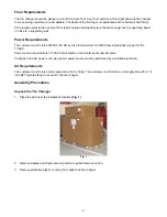
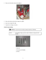
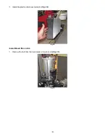
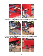
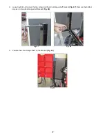
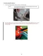
Remove the rear air line manifold cover
(Fig. 36 - Fig. 37)
.
Fig. 36 Fig. 37
3.
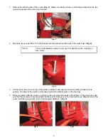
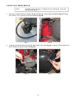
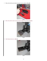
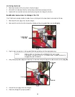
Position the wheel lift valve and pedal assembly near the side of the tire changer
(Fig. 38)
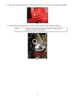
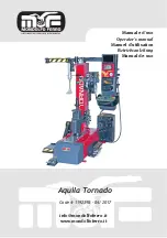
. Route the wheel lift
pedal air lines into the tire changer base
(Fig. 39)
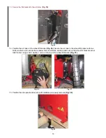
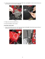
. Continue routing the air lines above the motor bracket
(Fig. 40 - Fig. 41)
.
Route them so they are on the belt side of the transmission. Not around the back side.
Fig. 38 Fig. 39
Fig. 40 Fig. 41


