16
4.
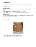
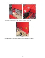
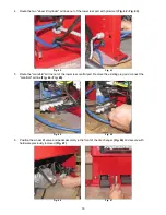
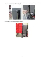
Route the two "wheel lift cylinder" air lines out of the lower rear port with grommet
(Fig. 42 - Fig. 43)
.
Fig. 42 Fig. 43
5.
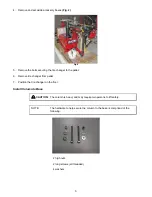
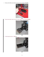
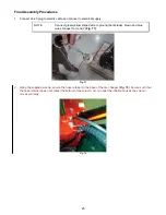
Route the "manifold" air line out of the lower rear central port. Remove the existing plug and connect the
"manifold" air line
(Fig. 44 - Fig. 45)
.
Fig. 44 Fig. 45
6.
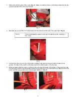
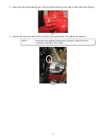
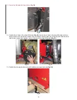
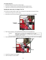
Position the wheel lift valve and pedal assembly in the front of the tire changer
(Fig. 46)
and secure with
hardware previously removed
(Fig. 47)
.
Fig. 46 Fig. 47

